


Single Module UPS Installation
11
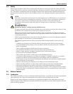
1.7 Control Cables and Communication
1.7.1 Monitor Board Features
Based on your site’s specific needs, the UPS may require auxiliary connections to manage the battery
system (external battery circuit breaker, battery temperature sensor), communicate with a personal
computer or provide alarm signaling to external devices or for Remote Emergency Power Off (REPO).
The monitor board, arranged for this purpose, is located on the rear of the operator access door. The
main features are:
• Input and Output dry contacts signal (one pair of contacts of relay)
• Emergency Power Off control (EPO)
• Environmental parameter input interface
• User communication (for data setting and user background monitor)
• Intellislot™ interface
• Modem interface
• Temperature detect interface
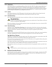
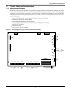
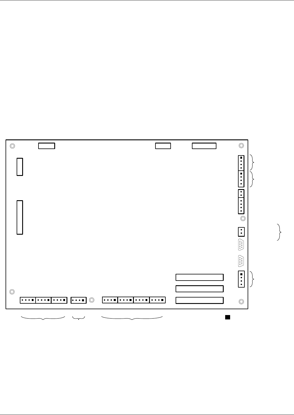
Figure 2 Monitoring board (U2) auxiliary terminal block detail
Intellislot 2
Intellislot 1
Intellislot 3
J1J3
J22
J23
J12
J9
X4
J15
J16
J17
J24
J10J30J26J4J28J25J21
J13
Dry In MBC BCB
BFP INV ACF
EPO
X1 X2 X3
J2
LCD
J8
X7
X6
X5
X4
PWR
Modem
SNMP Card
The black square ( )
on each slot indicates Pin 1.