


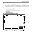

Single Module UPS Installation
15
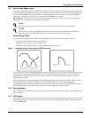
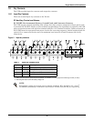
switch between these two terminals using shielded cable (see Figure 4 and Table 7). If this function
is not used, terminals X2: 3&4 must be opened and X2: 1&2 must be closed.
X5: Auxiliary DC Power Output
Auxiliary DC power for modem or external SNMP card. The voltage is between 9V to 12V. The maxi-
mum current is 500mA.
X6: Analog Input Interface
Two analog signal channels with an input range is from 0 to +12V. The precision of detection is ÷3%.
• X6 pin 1: Not used
• X6 pin 2: +12V
• X6 pin 3: ENV-T – environment temperature detection
• X6 pin 4: GND
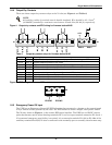
X7: External Battery Temperature Detector Interface
Interface for TMP12Z temperature detector, normally connected to an external battery cabinet (see
Figure 26).
Pin reference:
• X7 pin 1: Not used
• X7 pin 2: +12V (Power supply for Temperature Monitoring Probe)
• X7 pin 3: BAT-T (Battery Temperature signal)
• X7 pin 4: GND
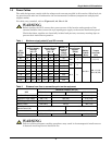
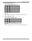
Table 7 EPO input contact relays
Position Name
Description
J28.1 EPO_NC EPO Activated when opened to J28.2
J28.2 EPO_NC EPO Activated when opened to J28.1
J28.3 EPO_NO EPO Activated when shorted to J28.4
J28.4 EPO_NO EPO Activated when shorted to J28.3
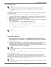
NOTE
The emergency stop action within the UPS shuts down the rectifier, inverter and static bypass.
It does not internally disconnect the input power supply. To disconnect ALL power to the UPS,
open the upstream feeder breaker(s) when the remote EPO is activated.
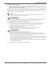
NOTE
Normally closed EPO – X2: 1,2, these terminals are supplied factory-linked on the monitor
board and must remain installed if using NC contacts.
NOTE
All auxiliary cables of terminal must be double insulated. Wire should be 0.5-1.5mm
2
(16-20AWG) stranded for maximum runs between 25 and 50 meters (82-164ft.) respectively.