


Options—For Assembly Inside the UPS Cabinet
110
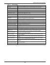
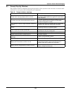
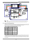
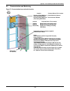
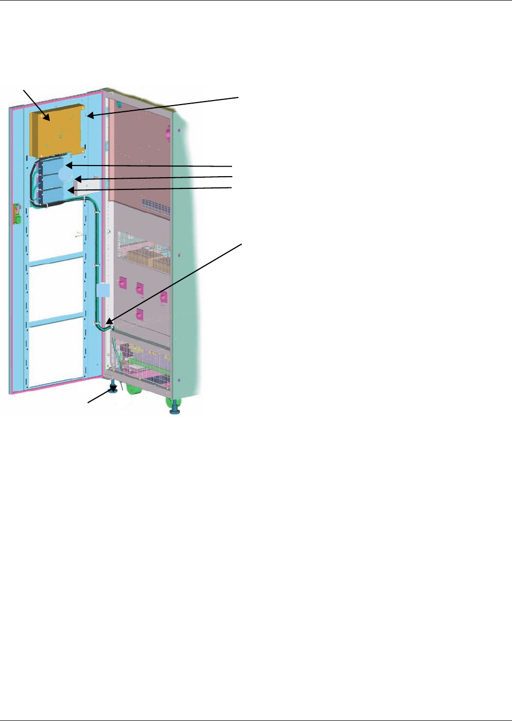
9.2 Communication and Monitoring
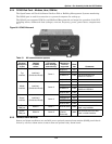
Figure 76 Communication bays and cable location
(
=
Notes:
a) All Intellislot cards are supported in any bay.
b) Port sharing is:
- PERMITTED between RS232-x DB9 devices and Relay /
Multiport4 Intellislot cards (i.e., Serial Multilink software
will work from RS232-1 DB9 also when relay card is
inserted in the top bay.
- NOT PERMITTED between RS-232-x D-B9 devices and
OCWeb / OC485 cards (i.e., Serial MultiLink software will
not work from RS232-1 DB-9 when OCWeb card is inserted
in the top bay.
c) Monitor board firmware version will be m131 or greater.
The version may be verified from the UPS LCD (refer to
8.0 - Operator Control Panel and Display).
RS-232-1 DB-9 (COM Port 1) - Serial MultiLink Software
(Port Setting 2400 Baud)
RS-232-2 DB-9 (COM Port 2 - Service Access Software
(Port Setting 9600 Baud)
Top Bay
Mid Bay
Bottom Bay
Relay Card (no port setting req’d)
Multiport4 (no port setting req’d)
OCWeb LB / OC485 (port setting
2400 Baud)
Suggested routing of customer-supplied
communication cables
Gland plate
for cable exit
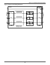
Preferred Device This LocationLocation
Preferred Device This LocationLocation
DB-9
Monitor
Board