


v
FIGURES
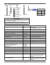
Figure i Model number nomenclature . . . . . . . . . . . . . . . . . . . . . . . . . . . . . . . . . . . . . . . . . . . . . . . . . . . . . . . ix
Figure 1 Residual current circuit breakers (RCCB) symbols . . . . . . . . . . . . . . . . . . . . . . . . . . . . . . . . . . . . . 7
Figure 2 Monitoring board (U2) auxiliary terminal block detail. . . . . . . . . . . . . . . . . . . . . . . . . . . . . . . . . . 11
Figure 3 Input dry contacts. . . . . . . . . . . . . . . . . . . . . . . . . . . . . . . . . . . . . . . . . . . . . . . . . . . . . . . . . . . . . . . 12
Figure 4 Output dry contacts and EPO wiring for firmware before M162. . . . . . . . . . . . . . . . . . . . . . . . . . 14
Figure 5 EPO wiring for firmware M200 or later . . . . . . . . . . . . . . . . . . . . . . . . . . . . . . . . . . . . . . . . . . . . . 14
Figure 6 Narrow battery cabinet with top and bottom cable entry locations. . . . . . . . . . . . . . . . . . . . . . . . 21
Figure 7 Narrow battery cabinet with top cable entry location . . . . . . . . . . . . . . . . . . . . . . . . . . . . . . . . . . 22
Figure 8 Wide battery cabinet with top and bottom cable entry locations. . . . . . . . . . . . . . . . . . . . . . . . . . 23
Figure 9 Wide battery cabinet with bottom cable entry location . . . . . . . . . . . . . . . . . . . . . . . . . . . . . . . . . 24
Figure 10 Wide battery cabinet with fuse or optional circuit breaker locations . . . . . . . . . . . . . . . . . . . . . . 25
Figure 11 Large battery cabinet dimensions . . . . . . . . . . . . . . . . . . . . . . . . . . . . . . . . . . . . . . . . . . . . . . . . . . 26
Figure 12 Large battery cabinet with fuse or optional circuit breaker locations . . . . . . . . . . . . . . . . . . . . . . 27
Figure 13 SENXA0NBCN4LCB.eps . . . . . . . . . . . . . . . . . . . . . . . . . . . . . . . . . . . . . . . . . . . . . . . . . . . . . . . . . 28
Figure 14 SENXA0NBCN4LF. . . . . . . . . . . . . . . . . . . . . . . . . . . . . . . . . . . . . . . . . . . . . . . . . . . . . . . . . . . . . . 29
Figure 15 SENXA0NBCN5LCB . . . . . . . . . . . . . . . . . . . . . . . . . . . . . . . . . . . . . . . . . . . . . . . . . . . . . . . . . . . . 30
Figure 16 SENXA0NBCN5LF. . . . . . . . . . . . . . . . . . . . . . . . . . . . . . . . . . . . . . . . . . . . . . . . . . . . . . . . . . . . . . 31
Figure 17 SENXA0NBCWXX3LCB . . . . . . . . . . . . . . . . . . . . . . . . . . . . . . . . . . . . . . . . . . . . . . . . . . . . . . . . . 32
Figure 18 SENXA0NBCWXX3LF . . . . . . . . . . . . . . . . . . . . . . . . . . . . . . . . . . . . . . . . . . . . . . . . . . . . . . . . . . . 33
Figure 19 SENXA0NBCWXX4LCB_2x4. . . . . . . . . . . . . . . . . . . . . . . . . . . . . . . . . . . . . . . . . . . . . . . . . . . . . . 34
Figure 20 SENXA0NBCWXX4LCB_4x2. . . . . . . . . . . . . . . . . . . . . . . . . . . . . . . . . . . . . . . . . . . . . . . . . . . . . . 35
Figure 21 SENXA0NBCWXX4LF_2x4 . . . . . . . . . . . . . . . . . . . . . . . . . . . . . . . . . . . . . . . . . . . . . . . . . . . . . . . 36
Figure 22 SENXA0NBCWXX4LF_4x2 . . . . . . . . . . . . . . . . . . . . . . . . . . . . . . . . . . . . . . . . . . . . . . . . . . . . . . . 37
Figure 23 Battery room design . . . . . . . . . . . . . . . . . . . . . . . . . . . . . . . . . . . . . . . . . . . . . . . . . . . . . . . . . . . . . 38
Figure 24 Battery circuit breaker box—30-120kVA and 140-200kVA . . . . . . . . . . . . . . . . . . . . . . . . . . . . . . 41
Figure 25 Battery circuit breaker box connection . . . . . . . . . . . . . . . . . . . . . . . . . . . . . . . . . . . . . . . . . . . . . . 42
Figure 26 Single temperature sensor and monitor board—U2 . . . . . . . . . . . . . . . . . . . . . . . . . . . . . . . . . . . . 43
Figure 27 Multiple temperature sensors, battery circuit breaker box and UPS module. . . . . . . . . . . . . . . . 44
Figure 28 Emergency power off connections . . . . . . . . . . . . . . . . . . . . . . . . . . . . . . . . . . . . . . . . . . . . . . . . . . 45
Figure 29 Typical 1+N system block diagram with common input supply, with separate batteries
and optional output / bypass distribution panel . . . . . . . . . . . . . . . . . . . . . . . . . . . . . . . . . . . . . . . 46
Figure 30 Dry contacts, multiple UPS modules with distribution panel . . . . . . . . . . . . . . . . . . . . . . . . . . . . 47
Figure 31 Connection of 1+N system parallel control cables. . . . . . . . . . . . . . . . . . . . . . . . . . . . . . . . . . . . . . 48
Figure 32 Hot standby configuration . . . . . . . . . . . . . . . . . . . . . . . . . . . . . . . . . . . . . . . . . . . . . . . . . . . . . . . . 49
Figure 33 Typical dual bus system configuration with static transfer switch and Load Bus Synch . . . . . . 50
Figure 34 Connections of a typical dual bus system utilising Load Bus Synch . . . . . . . . . . . . . . . . . . . . . . . 51
Figure 35 External maintenance bypass cabinet with separate bypass input. . . . . . . . . . . . . . . . . . . . . . . . 52
Figure 36 Equipment arrangement—UPS, battery cabinet and top-entry Isolation Transformer
Cabinet. . . . . . . . . . . . . . . . . . . . . . . . . . . . . . . . . . . . . . . . . . . . . . . . . . . . . . . . . . . . . . . . . . . . . . . . 53
Figure 37 Single input external isolation transformer cabinet. . . . . . . . . . . . . . . . . . . . . . . . . . . . . . . . . . . . 53
Figure 38 Dual input external isolation transformer cabinet . . . . . . . . . . . . . . . . . . . . . . . . . . . . . . . . . . . . . 54
Figure 39 Output external isolation transformer cabinet . . . . . . . . . . . . . . . . . . . . . . . . . . . . . . . . . . . . . . . . 54
Figure 40 Electrical connections . . . . . . . . . . . . . . . . . . . . . . . . . . . . . . . . . . . . . . . . . . . . . . . . . . . . . . . . . . . . 55
Figure 41 General arrangement—30-40kVA UPS. . . . . . . . . . . . . . . . . . . . . . . . . . . . . . . . . . . . . . . . . . . . . . 56
Figure 42 Front view, door open30-40kVA NX . . . . . . . . . . . . . . . . . . . . . . . . . . . . . . . . . . . . . . . . . . . . . . . . 57
Figure 43 Cable terminal layout—30-40kVA NX. . . . . . . . . . . . . . . . . . . . . . . . . . . . . . . . . . . . . . . . . . . . . . . 58
Figure 44 Location of parallel logic board M3 and options—30-40kVA NX. . . . . . . . . . . . . . . . . . . . . . . . . . 59
Figure 45 Internal battery layout and connections—30-40kVA NX. . . . . . . . . . . . . . . . . . . . . . . . . . . . . . . . 60
Figure 46 General arrangement—60-80kVA NX. . . . . . . . . . . . . . . . . . . . . . . . . . . . . . . . . . . . . . . . . . . . . . . 61