Options—For Assembly Inside the UPS Cabinet
106
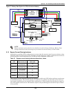
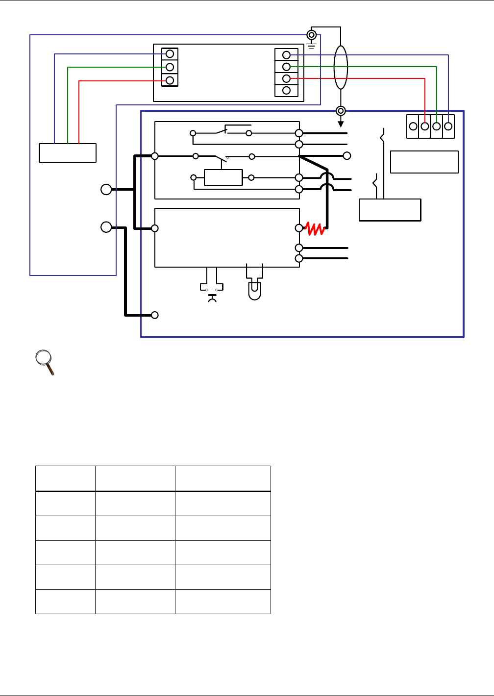
Figure 72 Battery Start Option for UPS with external battery
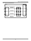
9.1.5 Bypass Current Sharing Inductors
Applicable in paralleled UPS configurations to ensure that the (passive) static bypass switches, when
activated, share the load current. The inductors provide droop type current compensation for the oth-
erwise inherent current dispersion due to SCR and cable impedance differences.
Three bypass current sharing inductors are assembled within each UPS cabinet without requirement
of additional footprint. The resulting degree of unbalance is typically less than 20% of the rated sys-
tem current depending on the external cable configuration. Cable lengths from the Bypass supply to
each UPS module and from the UPS module output to the paralleling point should be kept as identi-
cal as possible.
NOTE
Battery contactor opens after Inverter shutdown at end of battery discharge. Battery Start
settings disable the end of discharge trip command to external battery circuit breaker.
Table 26 Bypass current sharing inductors-dimensions, values
UPS
Dimensions
WxLxH, mm (in)
Inductor
Value (uH)
30/ 40 kVA
70x100x140
(2.8x3.9x5.5)
122
60/80 kVA
140x100x200
(5.5x3.9x7.9)
65
100/120kVA
210x100x250
(8.3x3.9x9.8)
40
140/160kVA
160x190x240
(6.3x7.5x9.4)
26
200kVA
160x190x240
(6.3x7.5x9.4)
22
Black-Start Resistor
Black-Start LED
AL6-M
Auxiliary Contact
Main Contact
Contactor
Control Coil
Battery Black-Start
Board
Contactor
Soft-In
Soft-Out
X2-1
X2-2
X1-1
X1-2
P-Bus
N-Line
N
NO
P
C
J15-2
J15-1
Batt-P
J12-33
+
J12-34
X7
234
Monitor Board
-U2
Detection Board
-M4
UPS
P-Bus
N-Line
Manual Press-Button
(AB6M)
Batt-N
+
Battery
Cabinet
Batt-N
-
Batt-P
+
OT6-4 LM35
Blue
Green
Red
1
2
3
GND IN P12
TMP-2
Temperature
Transport
OUT
P12
GND
3
2
4


