


Operating Procedures
84
7.5 UPS Self-Test
The UPS test procedure checks the control functions of the UPS, the mimic flow chart LEDs and the
audible alarm. This self-test is password controlled and menu driven. It can be carried out from the
UPS front panel by the operator and takes 5 seconds.
7.5.1 UPS Self-Test Procedure
1. Select “Commands” window on the UPS front panel.
Use the right or left arrow keys to navigate to the “Commands” window
2. Select desired Test.
Use “page” (F1) and up / down arrow keys (F2, F3) to highlight the desired test. Press “enter” (F4).
When prompted, enter each password digit with up arrow (F2) and use right arrow (F3) to access
next field. Press “enter” (F4) when all digits have been entered.
3. Wait until the test completes.
After 5 seconds, a popup window will appear to showing the result of this diagnosis: Rectifier,
Inverter, Monitor OK or Fault
4. Stop test.
If required, the test may be stopped before completion by selecting “Stop Test” in the “Commands”
window.
For more details on operating the UPS front panel, see 8.0 - Operator Control Panel and Display.
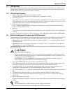
7.6 Maintenance Bypass Procedure and UPS Shutdown
The following procedure transfers the load supply from being protected by the UPS into being connected
directly to the AC input bypass supply though a maintenance bypass switch. This switch is either:
• internal (Q3- located behind the front door) for “Single module” or “1+1 redundant multi-module”
UPS applications.
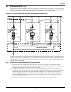
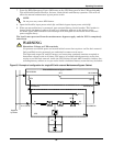
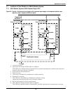
• external (located in the bypass cabinet) for “1+1 capacity” and “1+N redundant” multi-module
UPS applications – refer to Figure 64.
In multi-module systems—perform each step of the procedure in every UPS module before proceed-
ing to the next step.
1. Press INVERTER OFF direct access key on the UPS front panel.
The UPS inverter will shut down and the load is supplied through the Static Bypass supply.The
UPS Mimic indicator Inverter ON (4) will extinguish, the Status LED (6) turns on.
2. In “Single module” or “1+1 redundant” multi-module UPS—Close the internal maintenance
bypass power switch Q3 and any external maintenance bypass switch, if used.
3. In “1+N redundant” or “1+1 capacity” multi-module UPS—Close the external maintenance switch
only.
4. The Maintenance Bypass supply is now in parallel with the UPS Static Switch supply.
5. The display window will show messages reflecting the actions taken (i.e. Maintenance Bypass
closed, etc.).
6. Open output power switch Q5.
This ends the Bypass Procedure. The load is now powered directly from the Maintenance Bypass
supply.
Proceed with the following steps to shutdown the rectifier and battery.
!
CAUTION
Risk of Load Interruption
Except in emergency situations, so as not to risk a short interruption in powering the load,
before initiating this bypass procedure, confirm that no WARNING status is displayed in the
top right corner of the UPS Monitor.
If a WARNING status is displayed, the operator will be prompted to confirm (“enter”) or
cancel (“ESC”) any action that can lead to load interruption.
NOTE
The load equipment is NOT protected from AC supply aberrations.