


Single Module UPS Installation
13
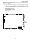
1.8.2 Maintenance Bypass Cabinet Interface
J26 and J30 are the MBC interface.
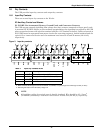
1.8.3 External Circuit-Breaker Interface
J10 is the interface to any external battery circuit breaker (BCB).
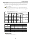
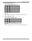
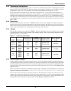
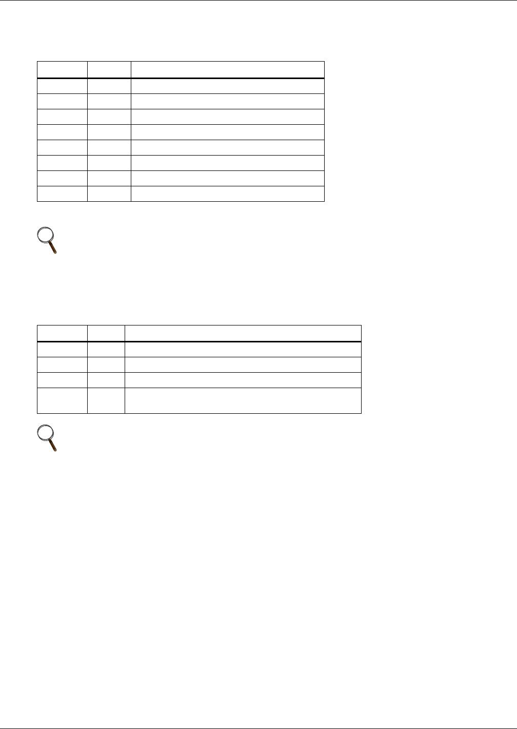
Table 4 Maintenance bypass cabinet interface
Position
Name
Description
J26.1 T_IT
1
Input transformer overtemperature (NC)
J26.2 AUX_I Reserved
J26.3 +12V +12V Power
J26.4 GND Power Ground
J30.1 FUSE Reserved
J30.2 F_FAN Fan Fail Alarm (NC)
J30.3 T_OT
1
Output Transformer Overtemperature (NC)
J30.4 AUX_O Reserved
1
- Must be configured by software before becoming active
NOTE
All auxiliary cables of terminal must be double-insulated. Wire should be 0.5-1.5mm
2
(16-20AWG) stranded for maximum runs between 25 and 50m (82-164 ft.) respectively.
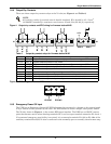
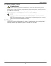
Table 5
External circuit-breaker interface
Position
Name
Description
J10.1 DRV BCB Driver Signal - Output (N.O.)
J10.2 FB BCB Contact State - Input (N.O.)
J10.3 GND Power Ground
J10.4 OL
BCB On-Line - Input - This pin will become active when
BCB interface is connected. (N.O.)
NOTE
All auxiliary cables of terminal must be double insulated. Wire should be 0.5-1.5mm
2
(16-20AWG) stranded for maximum runs between 25 and 50 meters (82-164ft.) respectively.