


Operating Procedures
86
7.7 Isolation of One Module in a Multi-Module System
7.7.1 Multi-Module Systems With External Output CB1
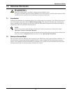
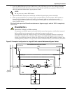
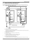
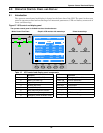
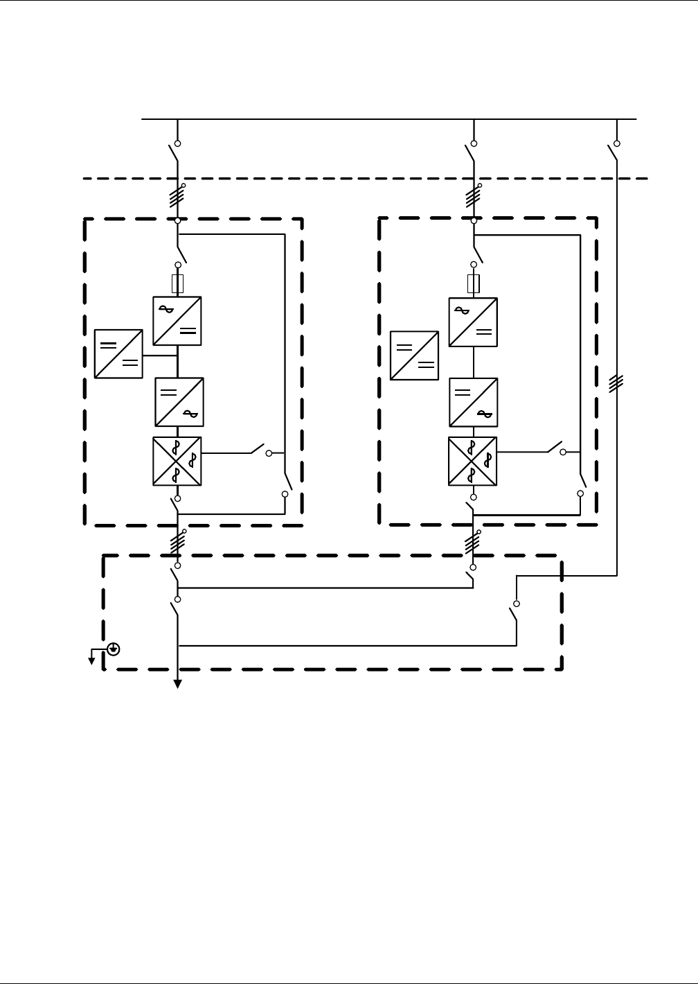
Figure 66 Typical 1+N system block diagram with common input supply, with separate batteries and
optional output / bypass distribution panel
1. Turn Off inverter.
2. Open External Output isolator (Q1ext or Q2ext).
The UPS enters Isolation Status automatically, parallel signaling and communication becomes
masked, and output becomes inhibited.
3. Power Off unit for maintenance.
4. Power On unit.
5. Unit enters Test Mode by configuration software setting.
6. Diagonosis or testing.
7. The UPS exits Test Mode by configuration software setting.
Output becomes inhabited because of Isolation Status.
8. Return all switches to the Normal position.
9. Close External Output isolator (Q1ext or Q2ext).
The UPS exits Isolation Status automatically, parallel signaling and communication recovers,
To Load
Distribution Cabinet
Supplied
by Others
Input Mains
Supply L1, L2, L3, N
UPS1
UPS2
Q1
Rectifier
Inverter
Charger
Q2
Q3
Q5
Q2
Q3
Q5
Rectifier
Inverter
Charger
Q1
Input Mains
Supply L1, L2, L3, N
L1, L2, L3, NL1, L2, L3, N
QUPS
QBYP
Q1EXT Q2EXT