


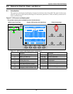
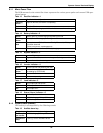
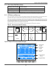
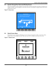

Operator Control Panel and Display
99
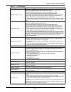
Bypass Unable to Trace
This alarm is triggered by an inverter software routine when the amplitude or
frequency of bypass voltage is beyond the normal range.
The amplitude threshold is fixed for positive and negative 10% rating.
This alarm automatically resets once the bypass voltage goes normal.
1. First verify that the bypass voltage and frequency displayed on the panel is within
the selected range. Note here the rated voltage and frequency are specified by
“Output voltage level” and “Output frequency level” respectively.
2. If the displayed voltage is believed to be abnormal, then verify the bypass voltage
and frequency presented to the UPS. Check the external supply if it is found to be
faulty.
Bypass Abnormal
This alarm is triggered by an inverter software routine when the amplitude or
frequency of bypass voltage exceeds the limit.
This alarm automatically resets once the bypass voltage goes normal.
First check if there are some relevant alarms such as “Bypass disconnect open”,
“Bypass phase reverse” and “Mains neutral lost”. If they appear, solve them first.
1. Then verify that the bypass voltage and frequency displayed on the panel is
within the bypass limit. Note here the rated voltage and frequency are specified by
“Output voltage level” and “Output frequency level” respectively.
2. If the displayed voltage is believed to be abnormal, then verify the bypass voltage
and frequency presented to the UPS. Check the external bypass supply if it is found
to be faulty. If the utility is likely to trigger this alarm frequently, the bypass limit can
be changed a little larger through the configuration software according to the
customer’s agreement.
Inverter Asynchronous
This alarm is triggered by an inverter software routine when the inverter and bypass
waveforms are misaligned by more than 6 degrees in phase. This alarm resets
automatically once the condition is no longer true.
1. First check if the alarm “Bypass unable to trace” or “Bypass abnormal” occurs. If
so, solve it first.
2. Verify the waveform of the bypass voltage. If it is too distorted, ask the customer
to verify and seek any possible measurements.
Inverter Fault Inverter output voltage beyond limits. Load transfers to bypass.
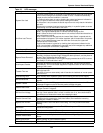
Inverter Overtemp.
The temperature of the inverter heat sink is too high to keep inverter running.
This alarm is triggered by the signal from a temperature monitoring thermostat on
the inverter bridge heat sink.
The UPS will recover automatically after a 5 minute delay from the disappearance
of the overtemperature signal.
If the overtemperature condition is true, then check for and verify:
1. high ambient air temperature.
2. blocked cooling airway.
3. any fan failure.
4. prolonged inverter overload
Fan Fault At least one of the cooling fans has failed
Inverter STS Fail
At least one of the static switches of inverter side is open or short circuit. This fault is
locked until power off.
Bypass STS Fail
At least one of the static switches of bypass side is open or short circuit. This fault is
locked until power off
Operation Invalid This record is registered following an incorrect operation:
Output Fuse Fail
At least one of the inverter output fuses is blown. Inverter shuts down. Load
transfers to bypass.
Control Power 2 Fail UPS operates but Redundant Control Power is not available.
Unit Over load
The UPS is confirmed to be overload when the load arises above 105% nominal
rating.
The alarm automatically resets once the overload condition is removed.
1. Confirm that the alarm is true by checking the load percent indicated on the LCD
panel to determine which phase is being overloaded.
2. If the alarm is true, measure the actual output current to verify that the indications
are valid.
Disconnect unnecessary load and ensure the safety. In a parallel system, a severe
load sharing error can also leads to the alarm.
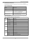
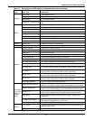
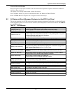
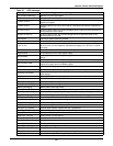
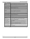
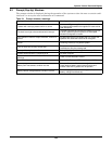
Table 23 UPS messages
Message Description / Suggested Action (if any)