REV. 5 7/6/2007
Liebert Monitoring Group –Development
20
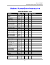
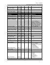
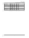
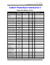
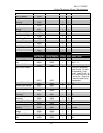
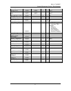
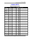
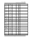
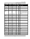
Voltage
Data Point
Input Register Holding Register # of Reg. Scale
Notes / Units
Number Of Input
Lines
30004 40004 1 1
Bits 12 - 15
Number Of
Bypass Lines
30004 40004 1 1
Bits 4 - 7
Number Of Output
Lines
30004 40004 1 1
Bits 8 - 11
Number Of
SubModules 30009 40009 1 1
Load Circuit
Present
30013 40013 1
There are 16 possible Load
Circuits. So each bit represents 1
load circuit. Load Circuit 1 is bit 0,
Load Circuit 2 is bit 1 and so on. If
the bit is 1 then the Load Circuit is
supported.
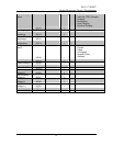
Battery Cabinet
Type
30018 40018 2 1
Battery Cabinet
Number 30019 40019 1 1
Battery AmpHour
30020 40020 1 1
AH
Nominal Power
Rating
30021 40021 2 1
VA
Nominal Input
Voltage
30027 40027 1 1
V
Nominal Output
Voltage
30028 40028 1 1
V
Nominal Static
Bypass Switch
Voltage
30029 40029 1 1
V
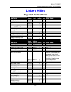
Nominal Input
Current
30030 40030 1 1
A
Nominal Input
Frequency
30031 40031 1 10
Hz
Nominal Output
Frequency
30032 40032 1 10
Hz
Nominal Power
Factor 30033 40033 1 100
Nominal Battery
Voltage
30034 40034 1 1
V
Auto Restart Delay
30051 40051 1 1
seconds
Device Low
Battery Time 30053 40053 1 1
min
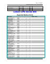
Load (Apparent
Power)
30102 2 1
VA
Load (Real Power)
30104 2 1
W
Load / Capacity
30106 1 1
%
Input Frequency
30107 1 10
Hz
Output Frequency
30108 1 10
Hz
Bypass Frequency
30109 1 10
Hz


