


Setup & Operation 3. Environments and Installation
24 G3 Rev.1
3.2 Base Table
A base table for anchoring the Manipulator is not supplied. Please make or obtain the
base table for your Manipulator. The shape and size of the base table differs depending
on the use of the robot system. For your reference, we list some Manipulator table
requirements here.
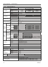
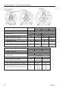
The torque and reaction force produced by the movement of the Manipulator are as
follows:
Max. Reaction torque on the horizontal plate : 500 Nm
Max. Horizontal reaction force : 2500 N
Max. Vertical reaction force : 1500 N
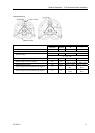
The threaded holes required for mounting the Manipulator base are M8. Use mounting
bolts with specifications conforming to ISO898-1 property class: 10.9 or 12.9.
For dimensions, refer to Setup & Operation: 3.3 Mounting Dimensions.
The plate for the Manipulator mounting face should be 20 mm thick or more and made of
steel to reduce vibration. The surface roughness of the steel plate should be 25 μm or
less.
The table must be secured on the floor or wall to prevent it from moving.
The Manipulator must be installed horizontally.
When using a leveler to adjust the height of the base table, use a screw with M16 diameter
or more.
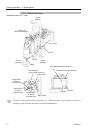
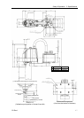
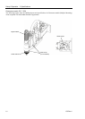
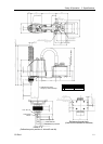
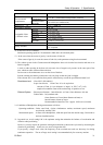
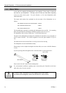
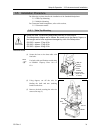
If you are passing cables through the holes on the base table, see the figures below.
[unit : mm]
Power Cable
Connector
Signal Cable
Connector
47
26
53
18
M/C Cables
Do not remove the M/C cables from the Manipulator.
For environmental conditions regarding space when placing the Controller on the base
table, refer to the Controller manual.
)
NOTE
WARNING
■
To ensure safety, a safeguard must be installed for the robot system.
For details on the safeguard, refer to the EPSON RC+ User’s Guide.