


Setup & Operation 3. Environments and Installation
26 G3 Rev.1
A
A
B
A
B
B
B
A
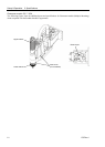
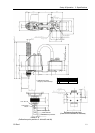
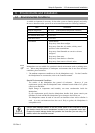
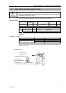
T
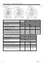
able Top Mounting
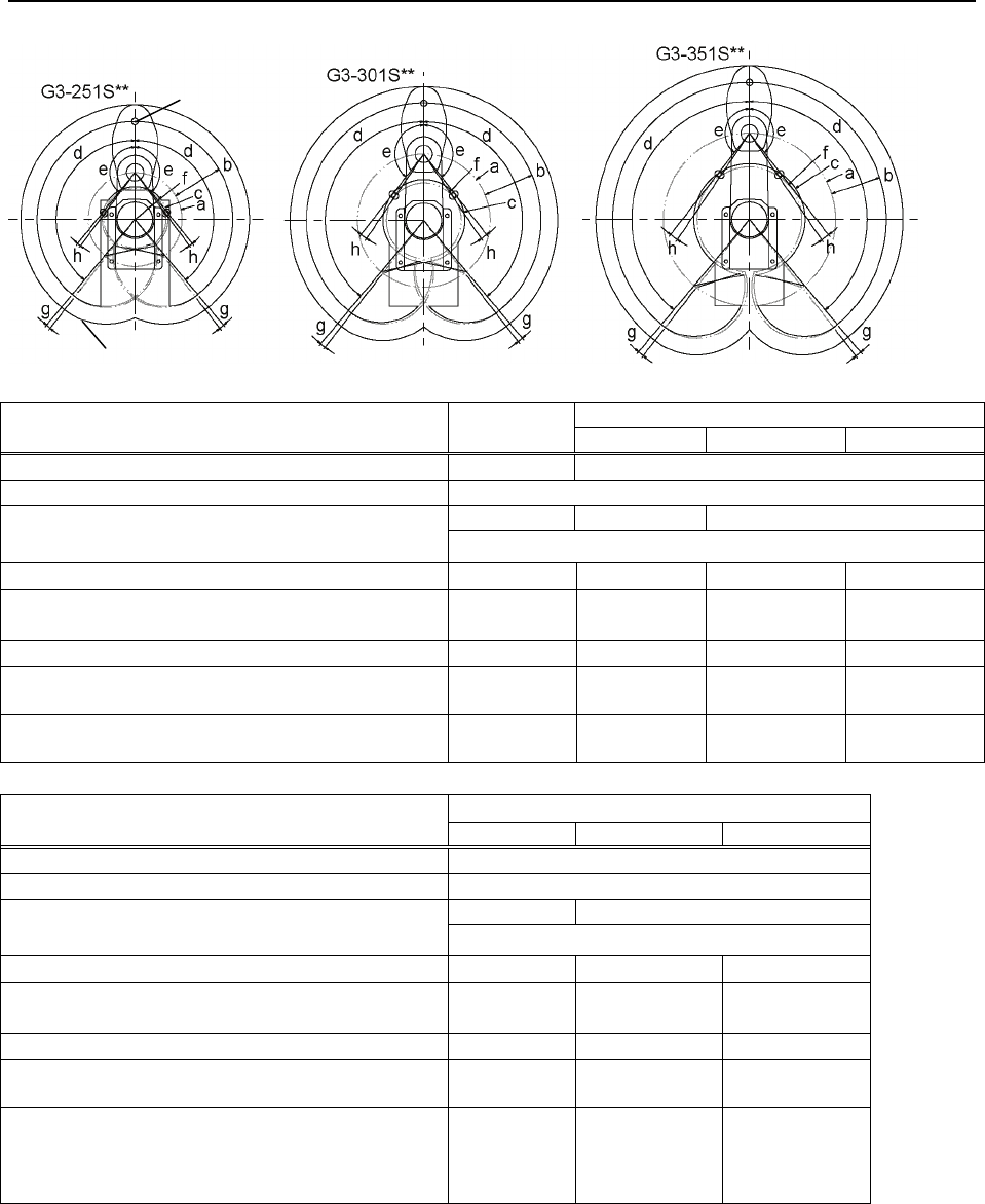
Center of Joint #3
Maximum space
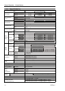
G3-301S/C
G3-251S/C
Standard -R -L
a
Length of Arm #1 (mm)
120 170
b
Length of Arm #2 (mm)
130
84 / 92 104.8 / 107.1 120.7
c
(Motion range)
Z : 150/120
d
Motion range of Joint #1 (degree)
140 140
−125 to +150 −150 to +125
e
Motion range of Joint #2 (degree)
141 / 137 142 / 141
−135 to +150
/ −135 to +145
−150 to +135
/ −145 to +135
f
(Mechanical stop area)
79.3 104.8 / 107.1 96.2 86.8
g
Joint #1 angle to hit mechanical stop (degree)
2 2
A:3
B:6
A:6
B:3
h
Joint #2 angle to hit mechanical stop (degree)
2.3 3.8
A:8.3
B:3.3
A:3.3
B:8.3
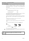
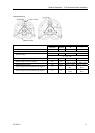
G3-351S/C
Standard -R -L
a
Length of Arm #1 (mm)
220
b
Length of Arm #2 (mm)
130
142.3 / 146.6 191.6
c
(Motion range)
Z : 150/120
d
Motion range of Joint #1 (degree)
140
−110 to +165 −165 to +110
e
Motion range of Joint #2 (degree)
−142
−120 to +165
/ −120 to+160
−165 to +120
f
(Mechanical stop area)
134.2 100.3 / 107.5 100.3 / 107.5
g
Joint #1 angle to hit mechanical stop (degree)
2
A:5
B:4
A:4
B:5
h
Joint #2 angle to hit mechanical stop (degree)
3.8
A:2.8
B:3.8
/ A:7.8
B:3.8
A:3.8
B:2.8
/ A:3.8
B:7.8