


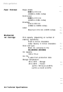
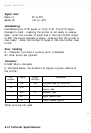
Interface Specifications
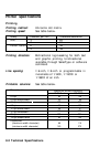
Parallel interface
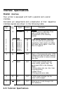
Your printer is equipped with both a parallel and a serial
interface.
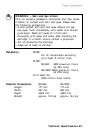
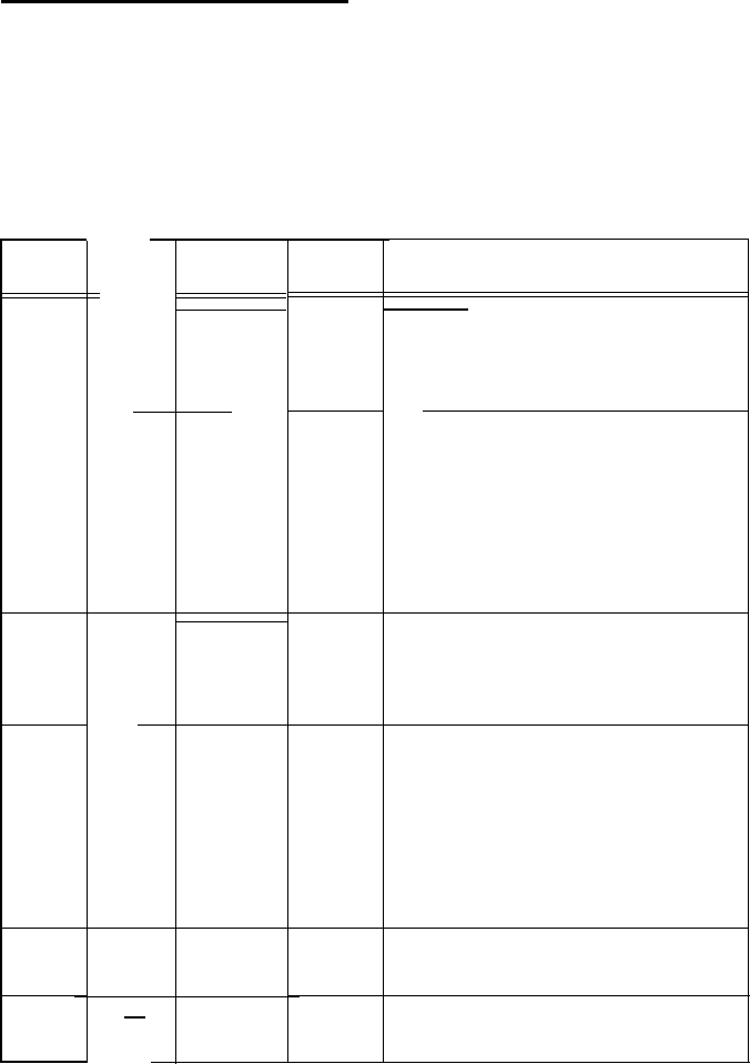
Connector pin assignments and a description of their respective
interface signals are shown in the following table.
Return
Pin
19
Signal
Pin
Signal
Direction
Description
STROBE
IN
IN
IN
IN
IN
IN
IN
IN
IN
STROBE pulse to read data. Pulse
width must be more than 0.5
microseconds at the receiving
terminal.
20
21
22
23
24
25
26
27
DATA 1
DATA 2
DATA 3
DATA 4
DATA 5
DATA 6
DATA 7
DATA 8
These signals represent information
of the 1st to 8th bits of parallel data,
respectively. Each signal is at HIGH
level when data is logical 1 and LOW
when it is logical 0.
1
2
3
4
5
6
7
8
9
10
11
28
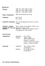
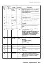
ACKNLG
OUT
About a 12-microsecond pulse. LOW
indicates that data has been received
and that the printer is ready to accept
more data.
29
BUSY
OUT
A HIGH signal indicates that the
printer cannot receive data. The
signal goes HIGH in the following
cases:
1) During data entry (ea. char. time)
2) During printing
3) When off line
4) During printer-error state
30
PE
A HIGH signal indicates that the
printer is out of paper.
12
13
OUT
SLCT OUT
Pulled up to +5 volts through 3.3K
ohm resistance.
8-10 Technical Specifications