


2-3Integration Scaling Matrix Switcher • Installation
Cabling and Rear Panel Views
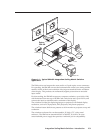
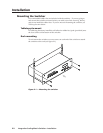
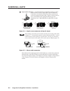
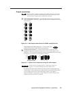
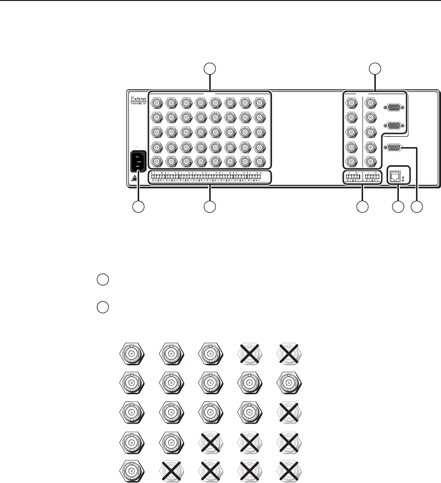
All connectors are on the rear panel (figure 2-2).
100
-
240
50/60 Hz
1.2A MAX.
12
H/HV
V
3
H/HV
V
INPUTS
4
H/HV
V
5
H/HV
V
6
H/HV
V
7
H/HV
V
R/R-Y
8
G/Y
VID
B/C
B-Y
R/R-Y
G/Y
VID
B/C
B-Y
R/R-Y
G/Y
VID
B/C
B-Y
R/R-Y
G/Y
VID
B/C
B-Y
R/R-Y
G/Y
VID
B/C
B-Y
R/R-Y
G/Y
VID
B/C
B-Y
R/R-Y
G/Y
VID
B/C
B-Y
R/R-Y
G/Y
VID
B/C
B-Y
H/HV
V
1
OUTPUTS
1
2
RS-232
2
2345678
H/HV
V
1
R
G
B
H/HV
V
R
G
B
H/HV
V
ETHERNET
LINK
AC
T
1 3 5 6
2 4
7
Figure 2-2 — ISM 482 rear panel connectors
Input connections
1
AC power connector — Plug a standard IEC power cord into this connector
to connect the switcher to a 100 to 240VAC, 50 Hz or 60 Hz power source.
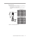
2
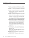
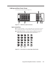
Input video connectors — Connect computer or RGB video, component
video, S-video, or composite video to these female BNC connectors.
Figure 2-3 shows how to connect the various video formats.
H/HV
RGBHV
Video
RGsB or
Component
Video
S-Video Composite
Video
RGBS or
RGBcvS
Video
V
H/HV
V
H/HV
V
H/HV
V
H/HV
V
R/R-Y
G/Y
VID
B/C
B-Y
R/R-Y
G/Y
VID
B/C
B-Y
R/R-Y
G/Y
VID
B/C
B-Y
R/R-Y
G/Y
VID
B/C
B-Y
R/R-Y
G/Y
VID
B/C
B-Y
Figure 2-3 — Connections for various input video formats