


B-7Integration Scaling Matrix Switcher • Reference Information
1
2
3
4
5
6
7
8
1
0
0
-
2
4
0
5
0
/
6
0
H
z
1
.
2
A
M
A
X
.
R
1
G
B
H/HV
R
2
G
B
H/HV
R
3
G
B
H/HV
R
INPUTS
4
G
B
H/HV
R
5
G
B
H/HV
R
6
G
B
H/HV
R
7
G
B
H/HV
R
8
G
B
H/HV
B
H/HV
V
H/HV
V
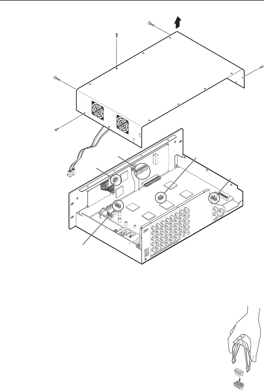
Remove (16)
screws.
Remove top two
front panel screws.
Lift cover straight up.
Extron
ISM 482
Switcher
U1
U2
J8
J13
Connect to
J8 and J13.
U100
U101
U6
U102
U103
U98
U99
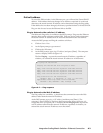
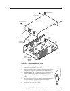
Figure B-1 — Removing the ISM cover
8. Locate the firmware chip(s) to be replaced on the main or
front panel circuit board (figure B-1).
9. After you are electrically grounded, use a DIP chip puller to
grasp the IC chip(s) and pull it (them) out of the socket.
10. Align the slots of the new firmware chip(s) with the angled
corners of the socket in the same orientation as the old
chip(s). Gently, but firmly, press the chip(s) into place in the
socket.
11. Reconnect the two fan power cords to connectors J8 and J13
on the main board. It does not matter which fan is
connected to which connector.
12. Replace the top cover on the ISM.
U102