


4-3Integration Scaling Matrix Switcher • Programmer’s Guide
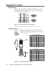
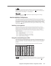
Ethernet connection
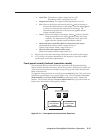
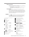
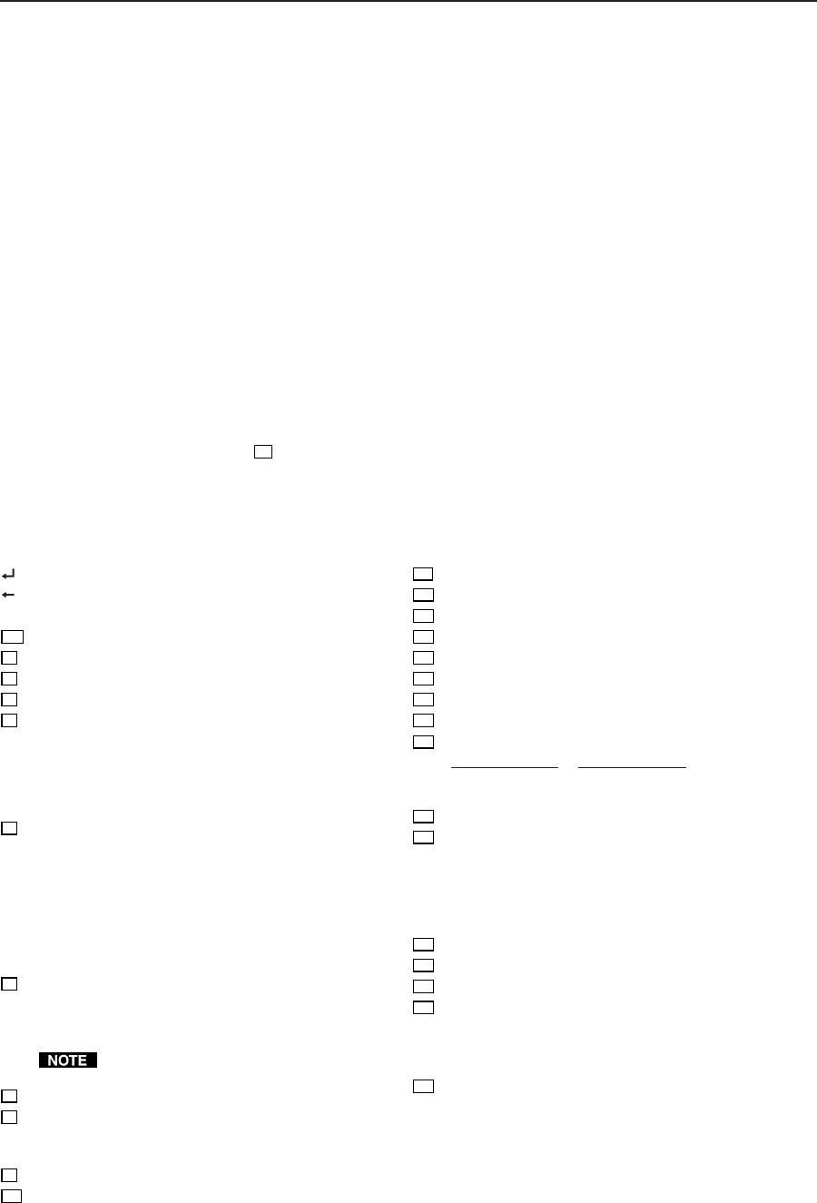
The cable can be terminated as either a patch cable or a crossover cable (figure 4-2)
and must be properly terminated for your application:
• Patch (straight) cable — Connection of the ISM to an Ethernet hub, router, or
switcher that also hosts a controlling computer.
• Crossover cable — Direct connection between the ISM and a computer.
Default address
To access the switcher via the Ethernet port, you will need the switcher’s IP
address. If the address has been changed to an address comprised of words and
characters, the
actual numeric IP address can be determined using the front panel
(see IP information in chapter 3, Operation) or the Ping utility (see
Ping to determine the
switcher’s IP address or Ping to determine the Web IP address in
appendix A
, Ethernet
Connection, for more details). If the address has not been changed, the factory-
specified default is 192.168.254.254.
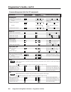
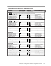
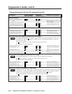
Symbols
Symbols (
X
n
values), defined below, are used throughout the discussions of the
switcher-initiated messages that begins on the next page and the command/
response table that begins on page 4-8. The symbols represent variables in the
switcher-initiated messages and the command/response table fields.
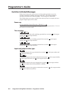
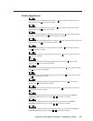
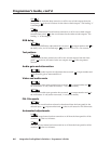
= CR/LF (carriage return/line feed) (hex 0D 0A)
= CR (no line feed)
• = Space
Esc
= Escape key
X1
= Input number 1 through 8
X2
= Output number 1 or 2
X3
= 000 = off, 001 = on
X4
= Input video type:
000 = RGB 005 = Betacam 60
001 = RGBcS 006 = HDTV
002 = YUVi 007 = S-video
003 = YUVp 008 = Composite
004 = Betacam 50
X5
= Scaler resolution:
00 = 640x480 08 = 1360x765
01 = 800x600 09 = 1365x1024
02 = 832x624 10 = 720p*
03 = 848x480 11 = 1080p
04 = 852x480 12 = 1080i
05 = 1024x768* 13 = 1400 x 1050
06 = 1280x768* 14 = 576p
07 = 1280x1024*
X6
= Video refresh rate:
000 = 50 Hz 003 = 75 Hz
001 = 56 Hz 004 = 85 Hz
002 = 60 Hz 005 = AFL*
Lock or AFL is Accu-RATE Frame Lock
™
(PAL = 50 Hz, NTSC =59.94 Hz)
X7
= Output video type: 00 = RGBHV, 01 = RGBS
X8
= Output sync polarity:
00 = H–/V– 02 = H+/V–
01 = H–/V+ 03 = H+/V+
X9
= Color value (0 thru 127)
X10
= Tint value (0 thru 255)
X11
= Brightness and contrast value (000 thru 63)
X12
= Size value (range depends on the resolution)
X13
= Centering value (range depends on the resolution)
X14
= Blanking value (000 thru 200)
X15
= Pixel sampling phase (000 through 031)
X16
= Horizontal filter value (000 thru 003)
X17
= Vertical filter or composite/S-video detail filter (001 thru 007)
X18
= Preset number (01 thru 03)
X19
= Output 1/ Output 2 selection:
Output 1/Output 2 Output 1/Output 2
00 = Off/Off 02 = Off/On
01 = On/Off 03 = On/On
X20
= RGB delay in 0.01 second steps (00 [no delay] to 50 [5.0 secs])
X21
= Test pattern type (1 through 10):
001 = Color Bars 006 = alternating pixels
002 = crosshatch 007 = film aspect ratio 1.78
003 = 4x4 crosshatch 008 = film aspect ratio 1.85
004 = gray scale 009 = film aspect ration 2.35
005 = crop 010 = ramp
X22
= Gain/attenuation (–24dB to +•9dB, each step = 1dB)
X23
= Gain value (numeric dB value, 0 to +9)
X24
= Attenuation value (numeric dB value, –1 to –24)
X25
= nnn.nn where
Hrt = horizontal rate (kHz)
Vrt = vertical rate (Hz)
xxx:xx means signal out of range
X26
= Detected input signal standard (0 through 4):
0 = none
1 = NTSC 3.58
2 = PAL
3 = NTSC 4.43
4 = SECAM
– = not applicable (occurs when the input is set
for RGB, YUV, or progressive YUV)