


Operation, cont’d
Integration Scaling Matrix Switcher • Operation3-2
Operation
Front Panel Controls and Indicators
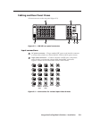
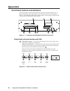
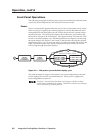
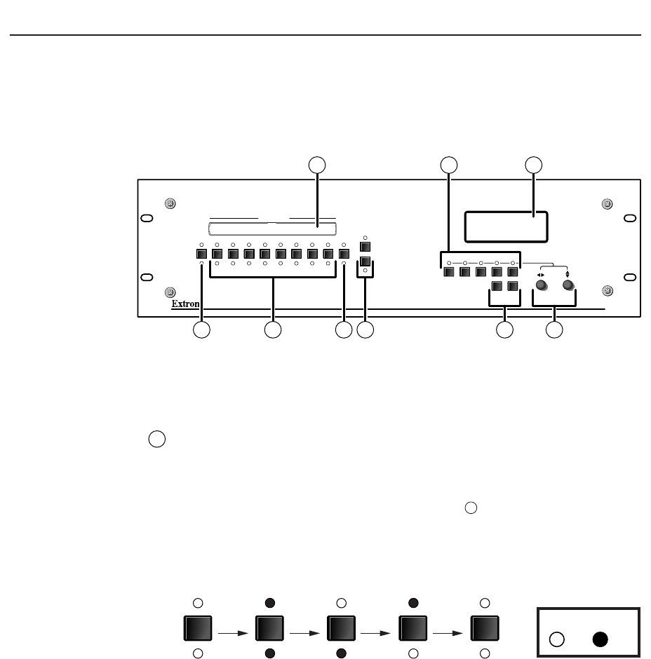
All of the switcher’s controls and indicators are on the front panel (figure 3-1). A
label window above the input buttons can be labeled with text and/or graphics.
The 20 x 4 LCD display indicates the switcher status, menu selections, the data rate,
and the status of additional system features.
ISM 482
INTEGRATION SEAMLESS SWITCHER
BLACK 1 2 3 4 5 6 7 8 VIDEO
1
2
OUTPUTS
12345678AUDIO
MUTE
COLOR/
TINT
BRT/
CONT
SIZE CENTER FILTER
ADJUST
MENU NEXT
INPUTS
ISM 482
15
73
4
6
2
8 9
Figure 3-1 — Integration Scaling Matrix Switcher front panel
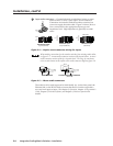
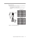
Video/Audio selection button and LEDs
1
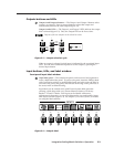
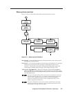
Video/Audio button — The Video/Audio button selects video, audio, video
and audio, or neither for creating ties.
Video and Audio LEDs — The green Video LED and red Audio LED indicate
whether video, audio, video and audio, or neither will be selected using the
Input buttons and indicated by the Input LEDs (
4
).
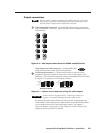
Figure 3-2 shows the sequence displayed by the LEDs when you cycle
through video and/or audio selection by pressing the Video/Audio button
repeatedly as follows.
Default
(Video &
audio)
VIDEO
AUDIO
Video
only
VIDEO
AUDIO
Audio
only
VIDEO
AUDIO
None
VIDEO
AUDIO
Video &
Audio
VIDEO
AUDIO
Press
button
Press
button
Press
button
Press
button
LED key:
= on, = off
Figure 3-2 — Video and/or audio selection cycle