


Reference Information, cont’d
Integration Scaling Matrix Switcher • Reference InformationB-6
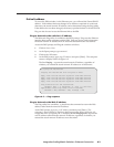
Firmware Upgrade Installation
In some cases the ISM’s firmware may require replacement with an updated
version. There are nine user-replaceable firmware chips, U1, U2, and U6 on the
front panel circuit board and U98, U99, U100, U101, U102, and U103 on the
main circuit board. The U-numbers are printed on the circuit boards. We
recommend that you send the unit in to Extron for service and updates.
• Chip set U1 and U2 are replaced as a pair.
• Chip U6 is replaced alone.
• Chip set U98, U99, U100, and U101 are replaced as a set.
• Chip set U102 and U103 are replaced as a pair.
CAUTION
Changes to firmware must be performed by authorized service personnel
only. Some ISM firmware updates must be performed at the Extron
factory.
Replace firmware in the ISM as follows:
1. Disconnect the AC power cord from the ISM to remove power from the unit.
To prevent electric shock, always unplug the ISM from the AC power
source before opening the enclosure.
2. If the ISM is installed in a rack, disconnect all signal and control cables and
remove the ISM from the rack.
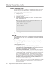
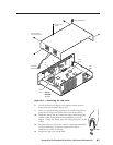
3. Remove the 16 screws, 8 on the top and 4 on each side of the ISM cover
(figure B-1).
4. Remove the top two front panel screws.
5. Lift the top cover straight up approximately five inches until you can access
the fan power cords.
CAUTION
Do not touch any switches or other electronic components inside the
ISM. Doing so could damage the switcher. Electrostatic discharge
(ESD) can damage IC chips even though you cannot feel it. You must be
electrically grounded before proceeding with firmware replacement. A
grounding wrist strap is recommended.
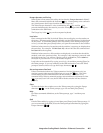
6. Disconnect the two fan power cords from connectors J8 and J13 on the main
board.
7. Lift the top cover out of the way.