


Operation, cont’d
Integration Seamless Switcher • Operation3-14
Auto Imaging and Auto Memories submenu
The Auto Imaging and Auto Memories menu provides a means to turn the auto
imaging and auto presets features on or off for all input selections.
If auto imaging is set to on, the ISS automatically sizes and centers the selected
input to fill the screen when a new frequency is input. If auto imaging is set off, the
ISS sizes and centers the selected input only when it is commanded using the input
button, see Auto imaging an input, earlier in this chapter. Rotate the Adjust
knob
to toggle auto imaging on or off for all input selections.
The auto memories feature saves and recalls centering, sizing, and filtering
information, based on the input frequency. Auto memory settings may conflict
with user preset settings. When you use a control system to switch inputs and then
recall a user memory, the delay in recalling the auto memory settings could result
in the recalled auto memory settings overwriting the recalled user memory settings.
To prevent this conflict, turn auto memories off. Rotate the Adjust
knob to toggle
auto memories on or off
Enhanced Mode submenu
The Enhanced Mode submenu provides a means to turn enhanced mode on or off.
Enhanced mode is an automatic gain control for S-video or composite video input
signals scaled and applied to the program output. If the input signal level is too
weak, the signal gain is increased; if the input signal level is strong, the signal gain
is decreased.
Use either the Adjust
or the Adjust knob to select among enhanced mode off or
on for the program output. The default is Off.
Enhanced mode is only effective for S-video and composite video input signals.
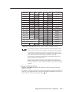
Pixel Phase submenu
The Pixel Phase submenu displays and lets you set the pixel phase, which is the
timing of the digital scaler’s sampling. Sampling at the optimum pixel phase
results in a brighter scaled output.
Use either the Adjust
or the Adjust knob to select the pixel phase for both
outputs simultaneously from 0 to 31. The default is 16.
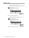
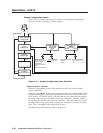
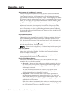
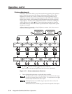
Preview Switch Mode submenu
The Preview Switch Mode submenu lets you set the way the preview output
responds to the cut or dissolve operation.
• Stay mode — When you initiate either a cut or dissolve operation, the video
and audio signals on the preview output are applied to the program output
(figure 3-14) and also continue to be applied to the preview output until
another input is selected.
The video input switches between the switcher’s two internal scalers,
resulting in a switching report being issued on the RS-232 port (see
Switcher-Initiated Messages in chapter 4, Operation).
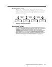
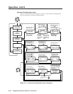
• Swap mode — When you initiate either a cut or dissolve operation, the
preview and program outputs are swapped (figure 3-14). The video and
audio signals on the preview output are applied to the program output. The
video and audio signals that had been applied to the program output are
applied to the preview output.
Each of the switcher’s two internal scalers retains the same video inputs; only
the outputs are swapped. No switching report is issued on the RS-232 port
(see Switcher-Initiated Messages in chapter 4, Operation).