


Integration Seamless Switcher • Maintenance and Modifications7-4
Maintenance and Modifications
5. Close the switcher. See Opening and Closing the Switcher, starting on step 9
on page 7-3.
DVI Output Card Installation
You can install an optional digital visual interface (DVI) output card in the ISS.
With the card installed, the program output outputs DVI video on a standard
DVI connector as well as the standard RGB video on BNC connector and 15-pin
HD connectors. We recommend that you send the unit to Extron for service and
updates.
Install an optional DVI output card in the ISS as follows:
Changes to electronic components must be performed by authorized
service personnel only.
To prevent electric shock, always unplug the ISS from the AC power
source before opening the enclosure.
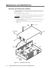
1. Open the switcher. See Opening and Closing the Switcher on page 7-2.
CAUTION
Do not touch any switches or other electronic components inside the ISS.
Doing so could damage the ISS. Electrostatic discharge (ESD) can
damage IC chips even though you cannot feel it. You must be
electrically grounded before proceeding with any electronic component
replacement. A grounding wrist strap is recommended.
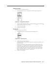
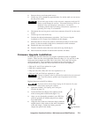
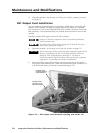
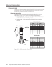
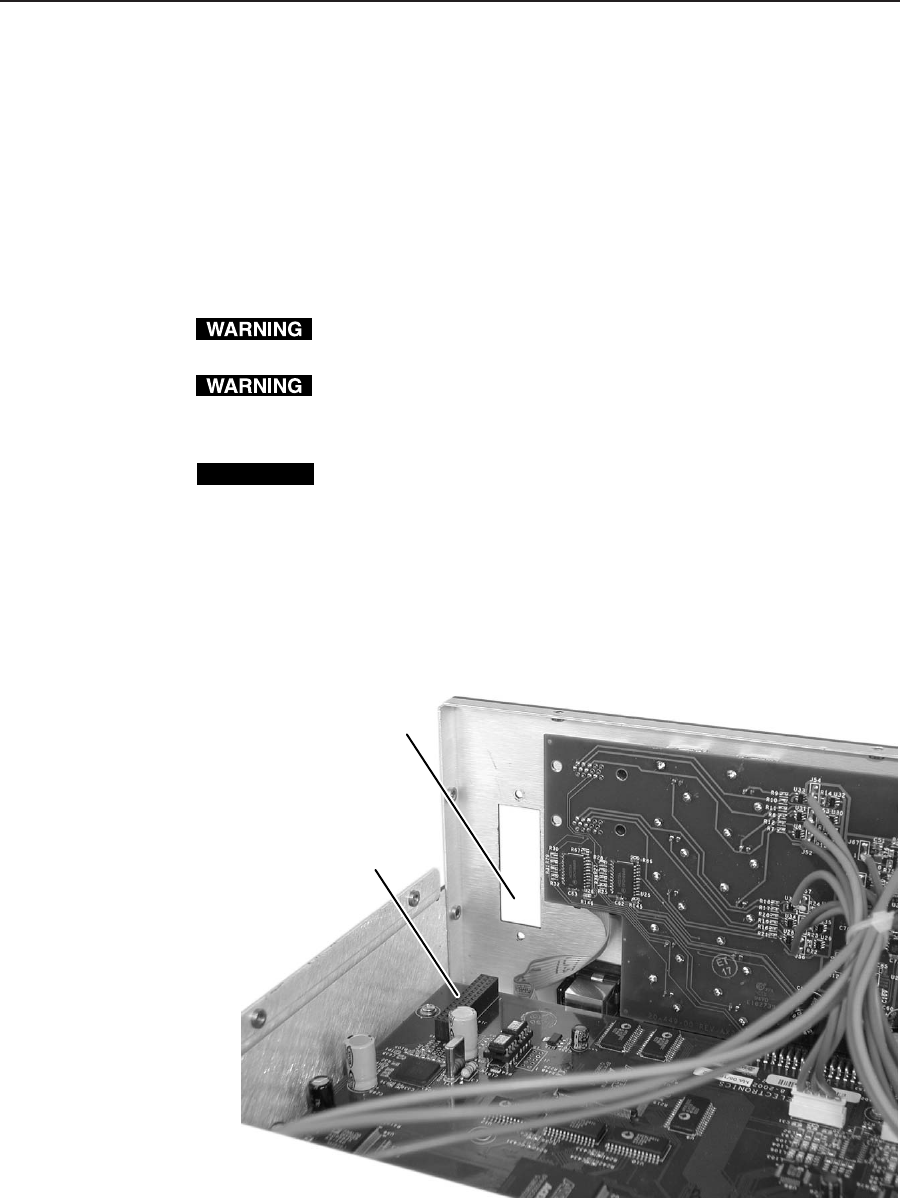
2. Locate the DVI output card connector opening on the rear panel and the
DVI output card connector J14. When viewed from the front, connector J14
is in the far left corner of the main circuit board (figure 7-2).
DVI Output Card
Connector J14 on
Main Circuit Board
DVI Output Card
Connector Opening
in ISS Rear Panel
Figure 7-2 — DVI output card connector opening and socket J14