


Matrix Software, cont’d
MVX Plus 128 VGA Matrix Switchers • Matrix Software
5-16
PRELIMINARY
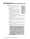
Tools menu
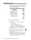
Assign device icons — Displays the complete set of input
and output device icons. You can drag any of these
icons to the input and output boxes.
Edit device palette — Allows you to add your own device
icon graphics.
RGB delay settings — Displays the switching interval
setting for each input and allows you to change them.
Audio-Input gain settings — Displays the audio gain
level setting for a single input or for all inputs and
allows you to change it. The level is expressed as
the magnitude (number of decibels) and polarity
(positive, gain or negative, attenuation) of the audio
adjustment.
Audio-Output volume settings — Displays the audio
output level setting for a single input or for all inputs
and allows you to change it. The level is expressed as a percentage of the
input audio volume that is applied to the output; 0% is full attenuation (audio
is silent), 100% is full volume.
View input frequencies — (DSVP) Displays the input horizontal and vertical
frequencies for each input.
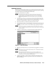
Update fi rmware — Allows you to replace the fi rmware that is coded on the
switcher’s control board without taking the switcher out of service, opening
the switcher enclosure, and replacing the fi rmware chip set. See Updating
fi rmware on page 5-13.
IP options — Allows you to set IP options. See IP Settings/Options window on
page 5-6.
HTML fi le manager — Displays a list of HTML fi les installed on the switcher and
allows you to upload custom fi les from a connected PC to the switcher. See
Uploading HTML fi les on page 5-14.
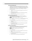
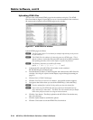
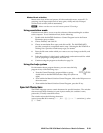
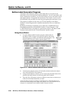
Hardware status — Provides an overall view of the status of the matrix switcher,
including the power supply voltages, the temperature status, the Remote
RS-232/RS-422 port confi guration, and the installed and updated fi rmware
status (fi gure 5-9).
Figure 5-9 — Status window