


MVX Plus 128 VGA Matrix Switchers • Ethernet Connection
A-2
Ethernet Connection
PRELIMINARY
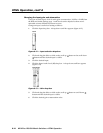
Ethernet Link
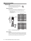
The rear panel Ethernet connector on the MVX Plus 128
switcher can be connected to an Ethernet LAN or WAN.
This connection makes SIS control of the switcher possible
using a computer connected to the same LAN.
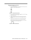
Ethernet connection
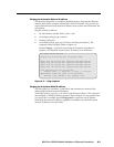
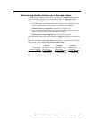
The Ethernet cable can be terminated as a straight-through cable or a crossover
cable and must be properly terminated for your application (fi gure A-1).
• Crossover cable — Direct connection between the computer and the
MVX Plus 128 switcher.
• Patch (straight-through) cable — Connection of the MVX Plus 128 switcher
to an Ethernet LAN.
Clip DownSide
1
1&2
3&6 4&5
7&8
2345678
1Pins 2345678
RJ-45
connector
Patch (straight) cable
Twisted
Pairs
Side 1 Side 2
Pin Wire color Pin Wire color
1 White-orange 1 White-orange
2 Orange 2 Orange
3 White-green 3 White-green
4 Blue 4 Blue
5 White-blue 5 White-blue
6 Green 6 Green
7 White-brown 7 White-brown
8 Brown 8 Brown
Crossover cable
Side 1 Side 2
Pin Wire color Pin Wire color
1 White-orange 1 White-green
2 Orange 2 Green
3 White-green 3 White-orange
4 Blue 4 Blue
5 White-blue 5 White-blue
6 Green 6 Orange
7 White-brown 7 White-brown
8 Brown 8 Brown
Figure A-1 — RJ-45 connector pinout tables
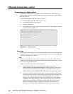
Default address
To access the MVX Plus 128 switcher via the Ethernet port, you need the switcher’s
IP address. If the address has been changed to an address comprised of words and
characters, you can determine the actual numeric IP address using the Ping utility.
If the address has not been changed, the factory-specifi ed default is 192.168.254.254.
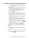
Ping can also be used to test the Ethernet link to the MVX Plus
128 switcher.
ACTLINK
ETHERNET