


MVX Plus 128 VGA Matrix Switchers • Installation
2-2
Installation
PRELIMINARY
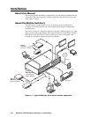
Mounting the Switcher
The matrix switchers are housed in rack-mountable, 2U high metal enclosures with
mounting fl anges for standard 19” racks. If desired, rack mount the switcher as
follows:
1. Insert the switcher into the rack, aligning the holes in the mounting bracket
with those in the rack.
2. Secure the switcher to the rack using the supplied bolts.
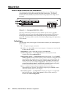
Cabling and Rear Panel Views
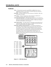
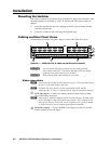
All connectors are on the rear panel. Figure 2-1 shows the MVX Plus 128 A.
INPUTS
OUTPUTS
RESET
RS232/RS422
REMOTE
LISTED
1T23
I.T.E.
1234 5678
9101112
LAN
1234 5678
1
2
3
4
5
6
7
8
9
10
11
12
1
2
3
4
5
6
7
8
INPUTS
OUTPUTS
8
6
7
5
1 2
43
REMOTE
Figure 2-1 — MVX Plus 128 A video and audio matrix switcher
C
Use Electrostatic discharge precautions (be electrically grounded)
when making connections. Electrostatic discharge (ESD) can damage
equipment, even if you cannot feel, see, or hear it.
C
Remove system power before making all connections.
Video connections
N
The switchers do not alter the video signal in any way. The signal output by the
switcher is in the same format as the input.
N
The MVX Plus 128 switchers can also switch RGBS, RGsB, RsGsBs,
component video, S-video, or composite video by using the appropriate adapters.
a
RGB video inputs — Connect the analog computer-video sources to these
15-pin HD female connectors.
N
Most laptop or notebook computers have an external video port, but they require
special commands to output the video to that connector. Also, a laptop’s screen
shuts off once that port is activated. See the computer’s user’s guide for details,
or contact Extron for a list of common laptop keyboard commands.
b
RGB video outputs — Connect RGBHV video displays to these 15-pin HD
female connectors for each output.