


Installation, cont’d
MVX Plus 128 VGA Matrix Switchers • Installation
2-4
PRELIMINARY
d
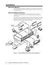
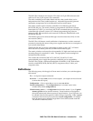
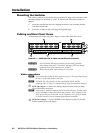
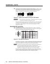
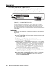
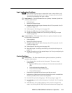
Connections for balanced and unbalanced audio outputs — These 3.5 mm,
5-pole captive screw connectors output the selected unamplifi ed, line level
audio. Connect audio devices, such as an audio amplifi er or powered
speakers. See fi gure 2-4 to properly wire an output connector.
Unbalanced Output
Tip
See caution
Sleeve
Tip
See caution
Balanced Output
Tip
Ring
Sleeve (s)
Tip
Ring
Figure 2-4 — Captive screw connector wiring for audio output
C
Connect the sleeve to ground (Gnd). Connecting the sleeve to a negative
(-) terminal will damage the audio output circuits.
The volume level for each output can be individually set via the front panel
or Ethernet or RS-232/RS-422 control. See chapter 3, Operation; chapter 4,
Programmer’s Guide; chapter 5, Switcher Software; and chapter 6, HTML
Operation for details.
RS-232/RS-422 connection
e
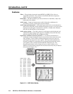
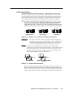
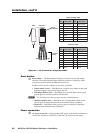
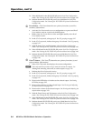
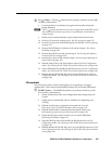
RS-232/RS-422 connector — Connect a host device, such as a computer,
touch panel control, or RS-232 capable PDA to the switcher via this 9-pin D
connector for serial RS-232/RS-422 control (fi gure 2-5).
RS-232FunctionPin Function
1
2
3
4
5
6
7
8
9
—
TX
RX
—
Gnd
—
—
—
—
Not used
Transmit data
Receive data
Not used
Signal ground
Not used
Not used
Not used
Not used
—
TX–
RX–
—
Gnd
—
RX+
TX+
—
Not used
Transmit data (–)
Receive data (–)
Not used
Signal ground
Not used
Receive data (+)
Transmit data (+)
Not used
RS-422
5
1
9
6
RS232/RS422
REMOTE
Figure 2-5 — RS-232/RS-422 connector
See chapter 4, Programmer’s Guide, for defi nitions of the SIS commands (serial
commands to control the switcher via this connector) and chapter 5, Matrix
Software, for details on how to install and use the control software.
N
The switcher can support either the RS-232 or RS-422 serial communication
protocol, and operate at 9600, 19200, 38400, or 115200 baud rates.
See Selecting the RS-232/RS-422 protocol and baud rate in chapter 3,
Operation, to confi gure the RS-232/RS-422 port from the front panel.
If desired, connect an MKP 2000 or MKP 3000 remote control panel to the
switcher’s RS-232/RS-422 connector. Refer to the MKP 2000 Remote Control
Panel User’s Manual and the MKP 3000 User’s Manual for details.