


Installation, cont’d
MVX Plus 128 VGA Matrix Switchers • Installation
2-6
PRELIMINARY
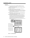
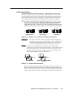
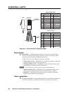
Clip DownSide
1
1&2
3&6 4&5
7&8
2345678
1Pins 2345678
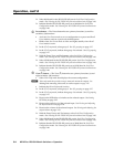
RJ-45
connector
Patch (straight) cable
Twisted
Pairs
Side 1 Side 2
Pin Wire color Pin Wire color
1 White-orange 1 White-orange
2 Orange 2 Orange
3 White-green 3 White-green
4 Blue 4 Blue
5 White-blue 5 White-blue
6 Green 6 Green
7 White-brown 7 White-brown
8 Brown 8 Brown
Crossover cable
Side 1 Side 2
Pin Wire color Pin Wire color
1 White-orange 1 White-green
2 Orange 2 Green
3 White-green 3 White-orange
4 Blue 4 Blue
5 White-blue 5 White-blue
6 Green 6 Orange
7 White-brown 7 White-brown
8 Brown 8 Brown
Figure 2-6 — RJ-45 connector and pinout tables
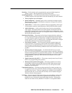
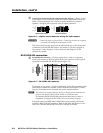
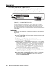
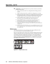
Reset button
g
Reset button — The Reset button initiates four levels of reset to the matrix
switcher. Press and hold the button while the switcher is running or while
you power up the switcher for different reset levels.
See Rear Panel Controls in chapter 3, Operation, for details.
• Events (mode 3) reset — Hold Reset for 3 seconds, then release it and push
it again to toggle events monitoring on and off.
• IP settings (mode 4) reset — Hold Reset for 6 seconds, then release it and
push it again to reset the switcher’s IP functions.
N
The IP settings reset does not replace any user-installed fi rmware.
• Absolute (mode 5) reset — Hold Reset for 9, seconds then release it and
push it again to restore the switcher to the default factory conditions.
• Hard reset — Hold Reset while powering up the switcher to restore the
switcher to the default factory conditions.
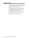
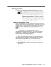
Power connection
h
AC power connector — Plug a standard IEC power cord into this connector to
connect the switcher to a 100 VAC to 240 VAC, 50 or 60 Hz power source.