


QS-1
MVX Plus 128 VGA Matrix Switchers • Quick Start
PRELIMINARY
Installation
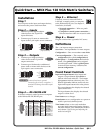
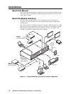
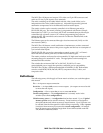
Step 1
Turn off power to the input and output devices,
and remove the power cords from them.
Step 2 — Inputs
a. Connect up to 12 high resolution
video inputs to the 15-pin HD
input connectors.
b. Connect up to 12 stereo or mono audio
inputs to the 5-pin captive screw connectors.
Step 3 — Outputs
a. Connect up to 8 high resolution
video devices to the 15-pin HD
output connectors.
b. Connect up to 8 balanced or unbalanced
stereo audio or mono audio devices to the
5-pin captive screw connectors.
Step 4 — RS-232/RS-422
If desired, connect a control system or computer
to the Remote RS-232/RS-422 port.
Step 5 — Ethernet
If desired, connect a network WAN or
LAN hub, a control system, or computer
to the Ethernet RJ-45 port. See chapter 2,
Installation, for details.
• Network connection — Wire as a patch
(straight) cable.
• Computer or control system connection —
Wire the interface cable as a crossover cable.
Step 6 — Power
Plug the switcher into a grounded AC source.
Defi nitions
Tie — An input-to-output connection.
Set of ties — An input tied to 2 or more outputs.
Confi guration — One or more ties or sets of ties.
Current confi guration — The currently active
confi guration (also called confi guration 0).
Global preset — A confi guration that has been
stored. One global preset can be assigned
to each input button. When a global preset
is retrieved from memory, it becomes the
current confi guration.
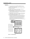
Front Panel Controls
Input and output buttons select inputs and
outputs. Output buttons light amber to
indicate video and audio ties. The buttons
light green to indicate video-only ties. The
buttons light red to indicate audio-only ties.
Input and output buttons also select presets.
The output buttons also display the selected
input’s audio level.
The input buttons also display the selected
output’s volume level.
Enter button saves changes.
Preset button saves a confi guration as a preset or
recalls a previously-defi ned preset.
View button selects a view-only mode that
prevents inadvertent confi guration changes.
On audio models, View decrements the level
and volume. See Viewing and adjusting the
audio level on QS-2.
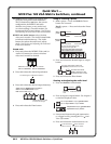
Quick Start — MVX Plus 128 VGA Matrix Switchers
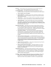
Unbalanced Input
Tip
Tip
Sleeve
Tip
Sleeve
Balanced Input
Ring
Sleeve(s)
Tip
Ring
(high impedance)(high impedance)
Unbalanced Output
Tip
See caution
Sleeve
Tip
See caution
Balanced Output
Tip
Ring
Sleeve(s)
Tip
Ring
C Connect the sleeve to ground.
Connecting the sleeve to a negative (-)
terminal will damage the audio output
circuits.
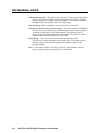
RS-232 Function Pin Function
1
2
3
4
5
6
7
8
9
—
TX
RX
—
Gnd
—
—
—
—
Not used
Transmit
Receive
Not used
Ground
Not used
Not used
Not used
Not used
—
TX–
RX–
—
Gnd
—
RX+
TX+
—
Not used
Transmit (–)
Receive (–)
Not used
Ground
Not used
Receive (+)
Transmit (+)
Not used
RS-422
5
1
9
6