


MVX Plus 128 VGA Matrix Switchers • Programmer’s Guide
4-2
SIS
™
Programming and Control
PRELIMINARY
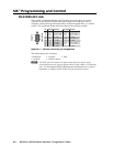
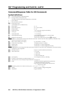
RS-232/RS-422 Link
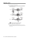
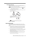
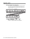
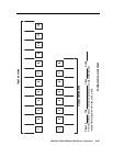
The switcher’s rear panel Remote 9-pin D female connector (fi gure 4-1) can be
connected to the RS-232 or RS-422 serial port output of a host device such as a
computer running the HyperTerminal utility, an RS-232 capable PDA, or a control
system. This connection makes software control of the switcher possible.
RS-232FunctionPin Function
1
2
3
4
5
6
7
8
9
—
TX
RX
—
Gnd
—
—
—
—
Not used
Transmit data
Receive data
Not used
Signal ground
Not used
Not used
Not used
Not used
—
TX–
RX–
—
Gnd
—
RX+
TX+
—
Not used
Transmit data (–)
Receive data (–)
Not used
Signal ground
Not used
Receive data (+)
Transmit data (+)
Not used
RS-422
5
1
9
6
RS232/RS422
REMOTE
Figure 4-1 — Remote connector pin assignments
The default protocol is as follows:
• 9600 baud • no parity • 8-bit
• 1 stop bit • no fl ow control
N
The MVX Plus 128 switcher can support either RS-232 or RS-422 serial
communication protocol, and can operate at 9600, 19200, 38400, or 115200 baud
rates. See Selecting the RS-232/RS-422 protocol and baud rate in chapter 3,
Operation, to confi gure the RS-232/RS-422 port from the front panel.