


IPL T SF24 and IPL T SFI244 • Installation and Operation
IPL T SF24 and IPL T SFI244 • Installation and Operation
Installation and Operation, cont’d
2-5
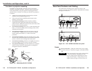
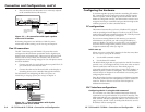
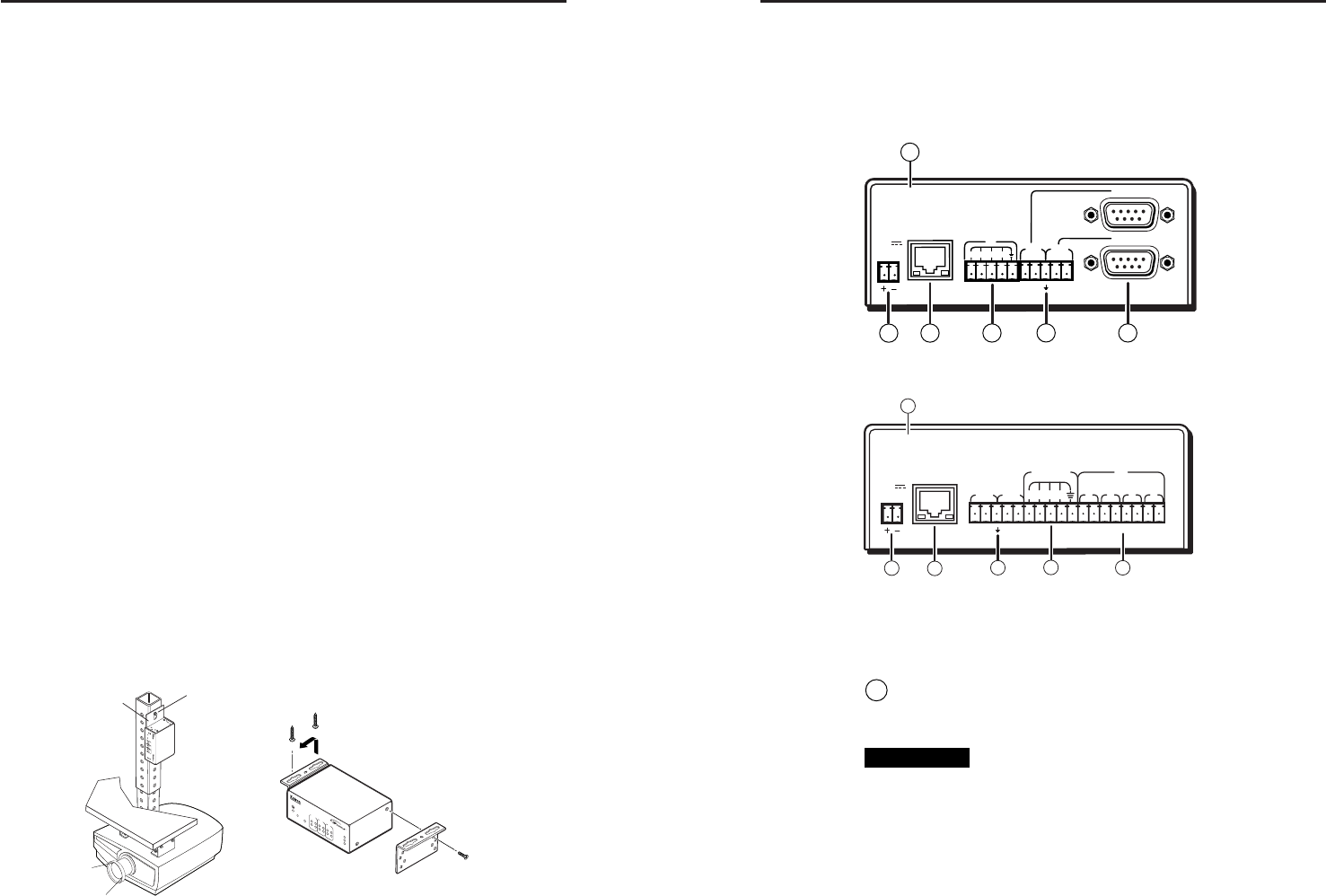
Rear Panel Features and Cabling
All connections, including power, input and output, and
control, are on the rear panel of the IPL T SF24 and IPL T SFI244.
See figures 2-4 and 2-5.
Figure 2-4 — IPL T SF24 rear panel
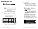
Figure 2-5 — IPL T SFI244 Interface rear panel
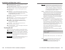
Power
1
Power connection — Plug the external 12V power supply
into this connector. The power supply is included with the
unit.
CAUTION
When connecting the power supply, voltage polarity
is extremely important. Applying power with
incorrect voltage polarity could damage the power
supply and the interface. Identify the power cord
negative lead by the ridges on the side of the cord.
COM1
LAN
00-05-A6-00-00-01
POWER
12V
.5A MAX
COM1
TX RX TX RX
COM2
4
COM2
1
I/O
2
3
5
7
1
3
4
2
COM1
TXRX TXRX
COM2
LAN
00-05-A6-00-06-25
POWER
12V
.5A MAX
FLEX I/O
2134 1
IR
2 3 4
GSGSGSGS
2
1
3
6
4
7
2-4
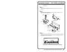
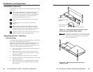
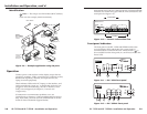
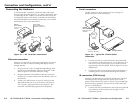
Furniture or projector mounting
In addition to using the IPL T unit on a rack, it can also be
furniture or projector mounted. Furniture mount or projector
mount the interface using the optional mounting kit (Extron
part #70-212-01, furniture, or Extron part #70-217-01, projector)
as follows:
1. Attach the mounting brackets to the interface with the
machine screws provided (figure 2-3).
2. If feet were previously installed on the bottom of the
interface, remove them.
3. For furniture mounting, hold the interface with the
attached brackets against the underside of the table or
other furniture. Mark the location of the screw holes of the
bracket on the mounting surface.
4. For furniture mounting, drill 3/32” (2 mm) diameter pilot
holes, 1/4” (6.3 mm) deep in the mounting surface at the
marked screw locations.
5. For furniture mounting, insert #8 wood screws into the
four pilot holes. Tighten each screw into the mounting
surface until just less than 1/4” of the screw head
protrudes.
6. For furniture mounting, align the mounting screws with
the slots in the brackets and place the interface against the
surface, with the screws through the bracket slots.
7. For furniture mounting, slide the unit slightly forward or
back, then tighten all four screws to secure it in place.
8. For projector mounting, secure the interface to a projector
mount or other surface by inserting the mounting bolt
through the bracket’s slotted hole.
Figure 2-3 — Mounting the IPL T SFI244
Projector Mount
Furniture Mount
IPL T SFI244
1
R
100
C
OM
TX
IR
LINK
ACT
2
RX
RTS
CTS
2
4
1
3
2
4
I/O
IR
IP
L
T
S
F
I2
4
4
1
R
1
0
0
C
O
M
T
X
L
I
N
K
A
C
T
2
R
X
1
3
2
4
1
3
2
4
I
/
O
I
R
Ceiling
Digital Projector
Mounting
Bolt
Projector
Mounting
Bracket