


IPL T SF24 and IPL T SFI244 • Quick Start Guide
Quick Start Guide — IPL T SF24, IPL T SFI244,
cont’d
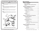
IPL T SF24 and IPL T SFI244 • Table of Contents
Chapter 1 • Introduction .......................................................... 1-1
About this Manual ................................................................ 1-2
About the IPL T SF24 and SFI244 Interfaces ............. 1-2
Features ......................................................................................1-3
Chapter 2 • Installation and Operation ........................ 2-1
Installation Overview .......................................................... 2-2
Mounting the IPL T Interface ........................................... 2-2
Rack mounting....................................................................... 2-2
Furniture or projector mounting .......................................... 2-4
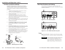
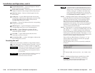
Rear Panel Features and Cabling ................................... 2-5
Power ..................................................................................... 2-5
Ethernet/LAN ......................................................................... 2-6
Serial communication ............................................................ 2-7
Identification ......................................................................... 2-8
Operation ................................................................................... 2-8
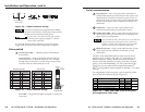
Front panel indicators ........................................................... 2-9
Resetting the unit ................................................................ 2-10
Chapter 3 • Connection and Configuration ...............3-1
Connecting the Hardware .................................................3-2
Ethernet connection .............................................................. 3-2
Serial connection ...................................................................3-3
IR connection (SFI244 only) ................................................... 3-3
Flex I/O connection ................................................................ 3-4
Configuring the Hardware ................................................ 3-5
PC configuration .................................................................... 3-5
Initial start up........................................................................ 3-5
IPL T interface configuration ................................................ 3-5
Configuring the IPL T interface using the ARP command . 3-5
Configuring the IPL T interface using direct PC connection3-7
Firmware upgrades................................................................3-8
Chapter 4 • Communication and Control ....................4-1
Ports Overview........................................................................4-2
Flex I/O ports .......................................................................... 4-2
Digital input .......................................................................... 4-3
Digital output........................................................................ 4-4
Analog input ......................................................................... 4-5
Bidirectional serial control interface ports .......................... 4-5
Table of Contents
iii
QS-2
Extron
IPL T RLY4
Relay Box
Lighting System
COM1
T
X
R
X
T
X
R
X
COM2
LAN
00
-0
5-A
6
-x
x-xx
-xx
POWER
12
V
.5A MAX
FLEX I/O
2
1
3
4
1
IR
2
3
4
GS
GSGS
G
S
Screen
Control
Extron
IPL T SFI244
Ethernet Control
Interface
RS-232
RS-232
DVD 1
VCR/
DVD 2
Extron
IR Emitters
Projector
Ethernet
Remote User
Control &
Administrator
Monitoring
TCP/IP
Network
Motion Detector
Extron
MLS 103 SV
S-video & Audio
Switcher
DSS Receiver
NO C NC
NO C NC
NO C NC
NO C NC
RELAY 1
RELAY 2
RELAY 3
RELAY 4
MLS 100 Series
MediaLink Switcher
AUX/MIX
LEVEL
INPUT SELECT
1
2
3
4
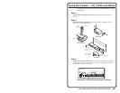
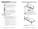
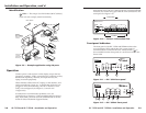
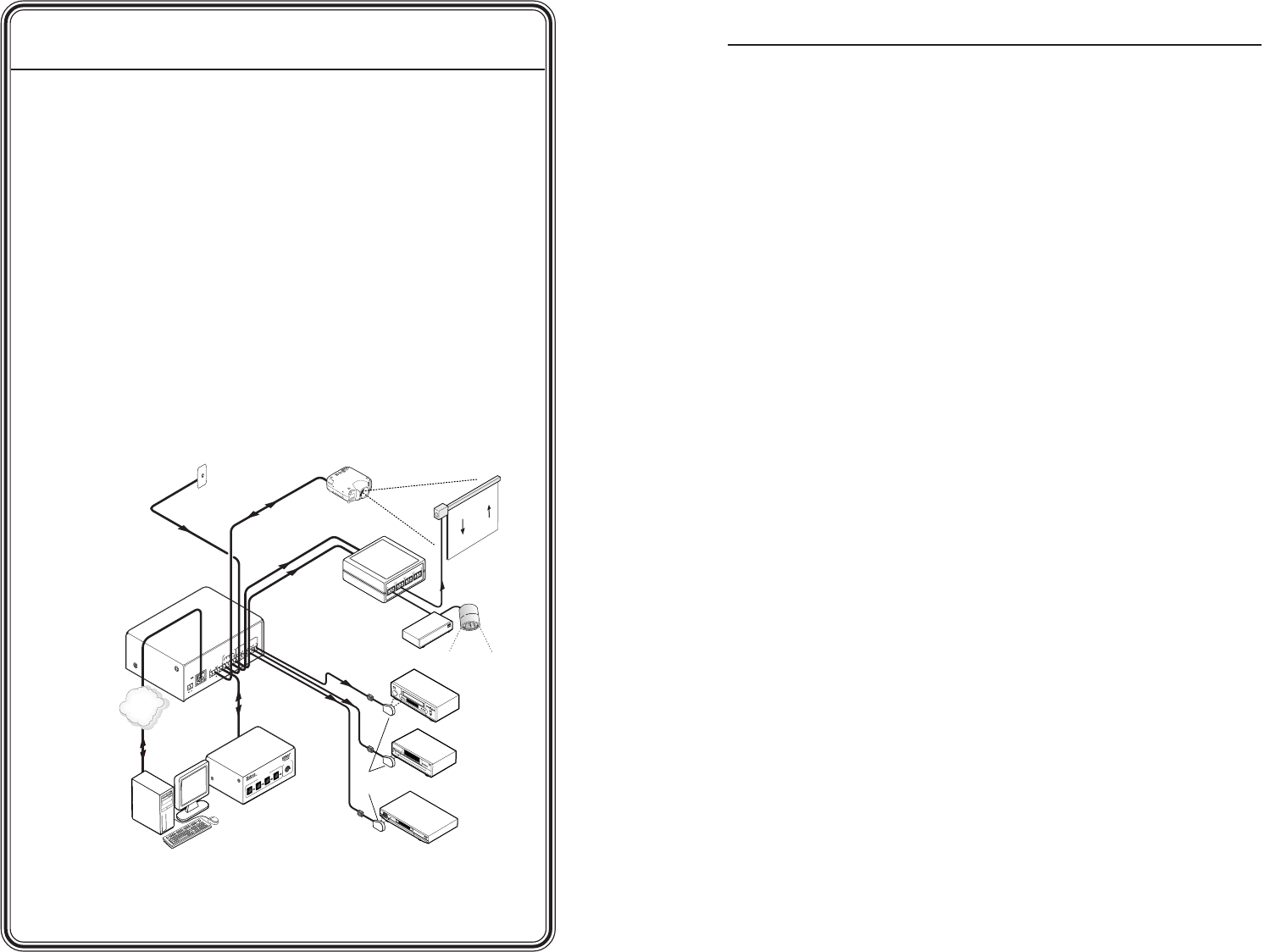
Step 4
Attach the serial communication cables from the IPL T unit to the
devices being controlled.
Step 5
Connect power cords and turn on the equipment in the following
order: output devices (projectors, monitors, speakers), the IPL T
interface, the serial controller or computer (PC), then all input
devices (DSS, cable boxes, etc.).
Step 6
Configure the IPL T interface using the ARP command. Refer to
IPL T interface configuration in chapter 3 for more information.
Step 7
Communicate with the IPL T interface via the default Web pages.
Refer to Communication with the interface in chapter 4 for more
information.
Typical connection setup (IPL T SFI244 shown)