


IPL T SF24 and IPL T SFI244 • Communication and Control
IPL T SF24 and IPL T SFI244 • Communication and Control
Communication and Control, cont’d
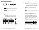
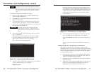
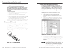
Digital input
When a Flex I/O port is configured as a digital input, the port is
set to measure two states: 1 or 0; On or Off; high or low. A
closed circuit = a logic 1 and an open circuit = a logic 0.
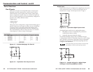
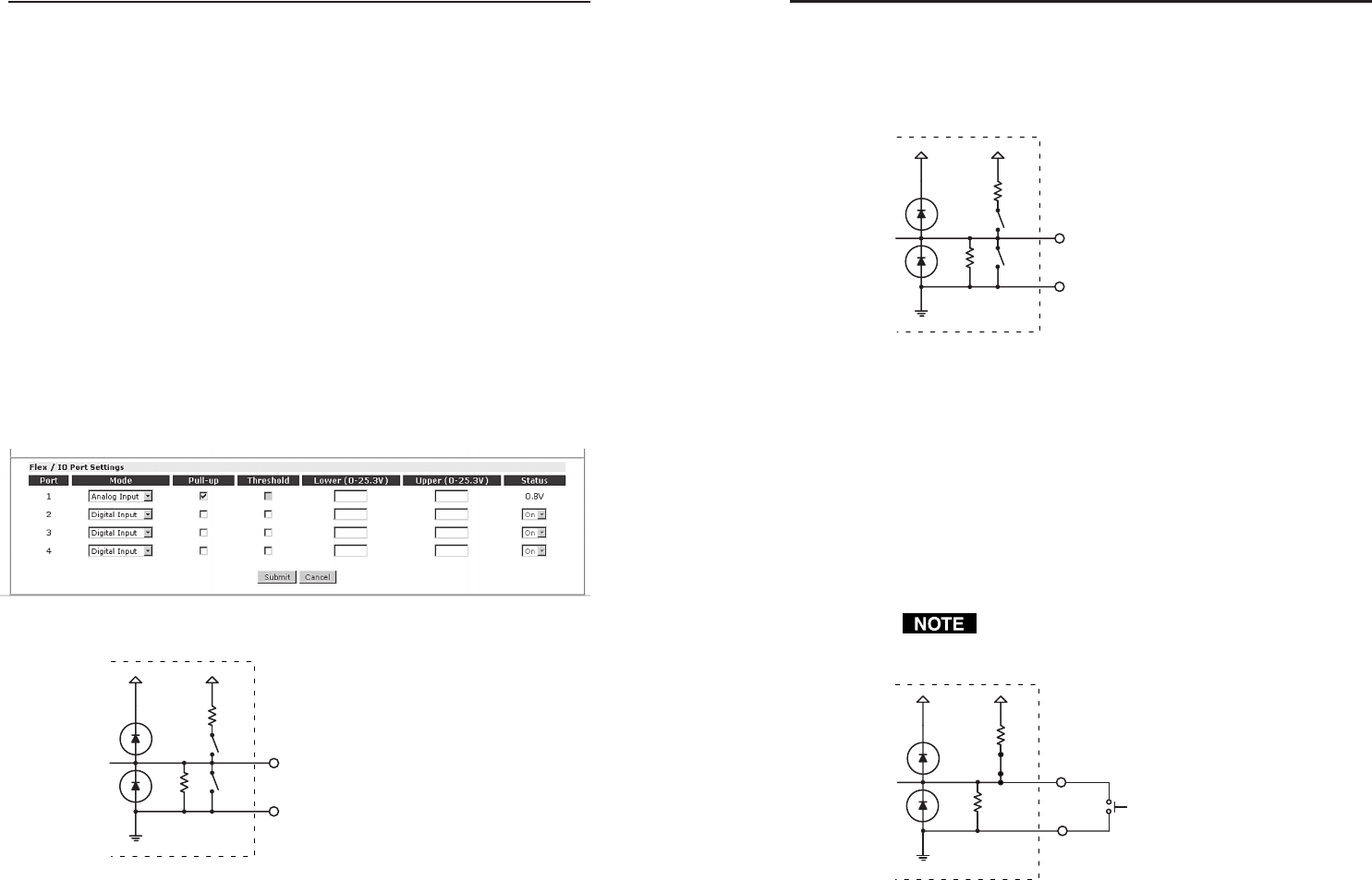
Figure 4-3 — equivalent digital input circuit
The Digital Input mode has two configurable options:
1. The ability to turn on an internal pull-up resistor to
+5VDC (shown below as SW2)
2. Adjustable detection threshold voltages
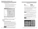
The default threshold voltages follow standard TTL logic:
a voltage below 0.8VDC is measured as logic low, and a voltage
above 2.0VDC is measured as logic high. Using an adjustable
threshold, the integrator can select the proper high and low
voltages for the installation.
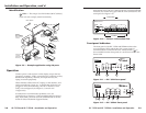
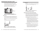
In the figure below, the SW2 switch is turned closed,
activating the +5VDC and 2K pull-up resistor.
Figure 4-4 — Sample wiring for a digital input
reading an external pushbutton switch
4-3
I/O
2K
+30V +5V
SW2
GND
24K
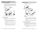
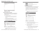
Ports Overview
Flex I/O ports
Extron Flex I/O ports are configurable input or output ports
designed to provide connectivity to various devices such as
motion detectors, alarms, lights, LEDs, buttons, photo (light)
sensors, temperature sensors, relays, etc. All Flex I/O ports are
tied to a common ground, but can be individually configured to
operate in one of three different modes:
• Digital Input
• Digital Output
• Analog Input
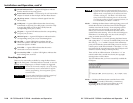
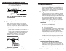
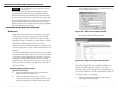
These ports can be configured by using the default Web pages of
the IPL T Web Server (see figure 4-1 below; also see Establishing
or changing system or port settings later in this chapter) or by
dynamically using the Simple Instruction Set commands (see
the Command/Response Table for Simple Instruction Set commands
in this chapter) via Telnet, scripts or Web pages.
Figure 4-1 — Default Web page for Flex I/O
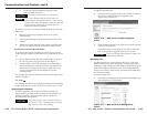
Figure 4-2 — Equivalent Flex I/O port circuit
4-2
24K SW1
2K
+30V +5V
SW2
I/O
GND
24K SW1
2K
+30V +5V
SW2
I/O
GND