


IPL T SF24 and IPL T SFI244 • Connection and Configuration
IPL T SF24 and IPL T SFI244 • Connection and Configuration
Connection and Configuration, cont’d
3-3
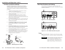
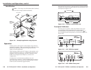
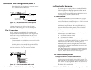
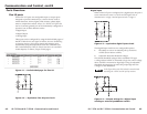
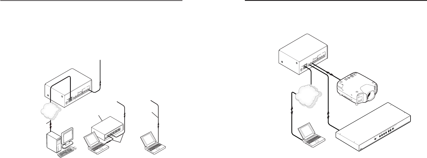
Serial connection
The IPL T interface can be connected to any existing A/V
product that has a serial control port.
Figure 3-2 — Typical IPL T SFI244 Serial
connection
1. Connect one end of a serial cable to the rear panel COM
port connector of the interface unit. As an alternative, you
can use a 3.5 mm, 5-pole captive screw connector wired
appropriately, where available. Refer to figure 2-8 for pin
assignments.
2. Connect the other end of the serial cable to the display or
switching device to be controlled through the interface.
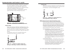
IR connection (SFI244 only)
Wiring for the IR emitter is provided by the IR ports. The IPL T
interface provides enough current to power up to four IR
emitters with a 100 foot run each, or at least 1 at up to 4000 feet.
IR control can be applied to devices such as VCRs, audio tape
players, or DVD players.
1. Connect one end of an IR emitter cable to the rear panel IR
port connector of the interface unit. See figure 3-3 for
connection options.
Extron
IPL T SFI244
Ethernet Control
Interface
User Control &
Administrator Monitoring
Ethernet
C
OM1
TX
RX TX
RX
CO
M2
LAN
00-05-A6-xx-xx-xx
POWER
12V
.5A MAX
FLEX I/O
2
1
3
4
1
IR
2
3
4
GS
G
S
G
S
G
S
C
R
OS
SP
O
IN
T
42
H
V
A
A
U
DIO
/ dB
VIDEO
/ dB
CO
NF/
S
A
VE
4
3
2
1
1
2
I/O
INPUT
S
O
UT
PU
TS
RS-232
Projector
Extron
Crosspoint Switcher
RS-232
TCP/IP
Network
3-2
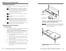
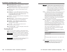
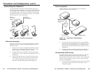
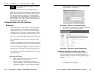
Connecting the Hardware
To connect the IPL T interface, connect the input and output
devices to the unit using figure 3-1 as a guide. Please note, prior
to connecting the IPL T unit to a local area network (LAN) you
must initially connect a PC directly to the IPL unit and change
the default IP address to an address specified by your network
administrator (for a LAN connection).
Figure 3-1 — IPL T interface connections
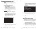
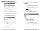
Ethernet connection
This type of connection is used on an ongoing basis to connect
the IPL T unit and to control switching and display devices
through the unit.
1. Plug one end of a Cat 5, straight-through Ethernet cable
into the rear panel Ethernet connector on the IPL T unit.
Refer to figure 2-7 for RJ-45 connector wiring.
2. Plug the other end of the Ethernet cable into a network
switch, hub, or router connected to an Ethernet LAN or to
the Internet.
3. Launch your Web browser on your PC and type in the
Web address that you set up on the IPL T unit (refer to
IPL T interface configuration later in this chapter). The
initial IPL T default Web page should be displayed.
COM1
TX
RX
TX
RX
COM2
LAN
00-05-A6-xx-xx-xx
POWER
12
V
.5A
M
A
X
FLEX I/O
2
1
3
4
1
IR
2
3
4
GS
GS
GS
G
S
Extron
IPL T SFI244
Ethernet Control
Interface
Ethernet
TCP/IP
Network
L
A
N
POWER
12
V
.5
A M
A
X
L
A
N
L
A
N
L
A
N
L
A
N
Hub/
Switch/Router
LAN
PC PC
or
or
Serial Cables
to Controlled Devices
(Switcher, Projector, etc.)
Crossover
Cable
Straight
Through
Cable
Straight
Through
Cable