


IPL T SF24 and IPL T SFI244 • Installation and Operation
IPL T SF24 and IPL T SFI244 • Installation and Operation
Installation and Operation
2-3
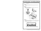
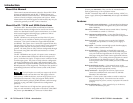
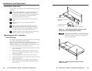
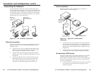
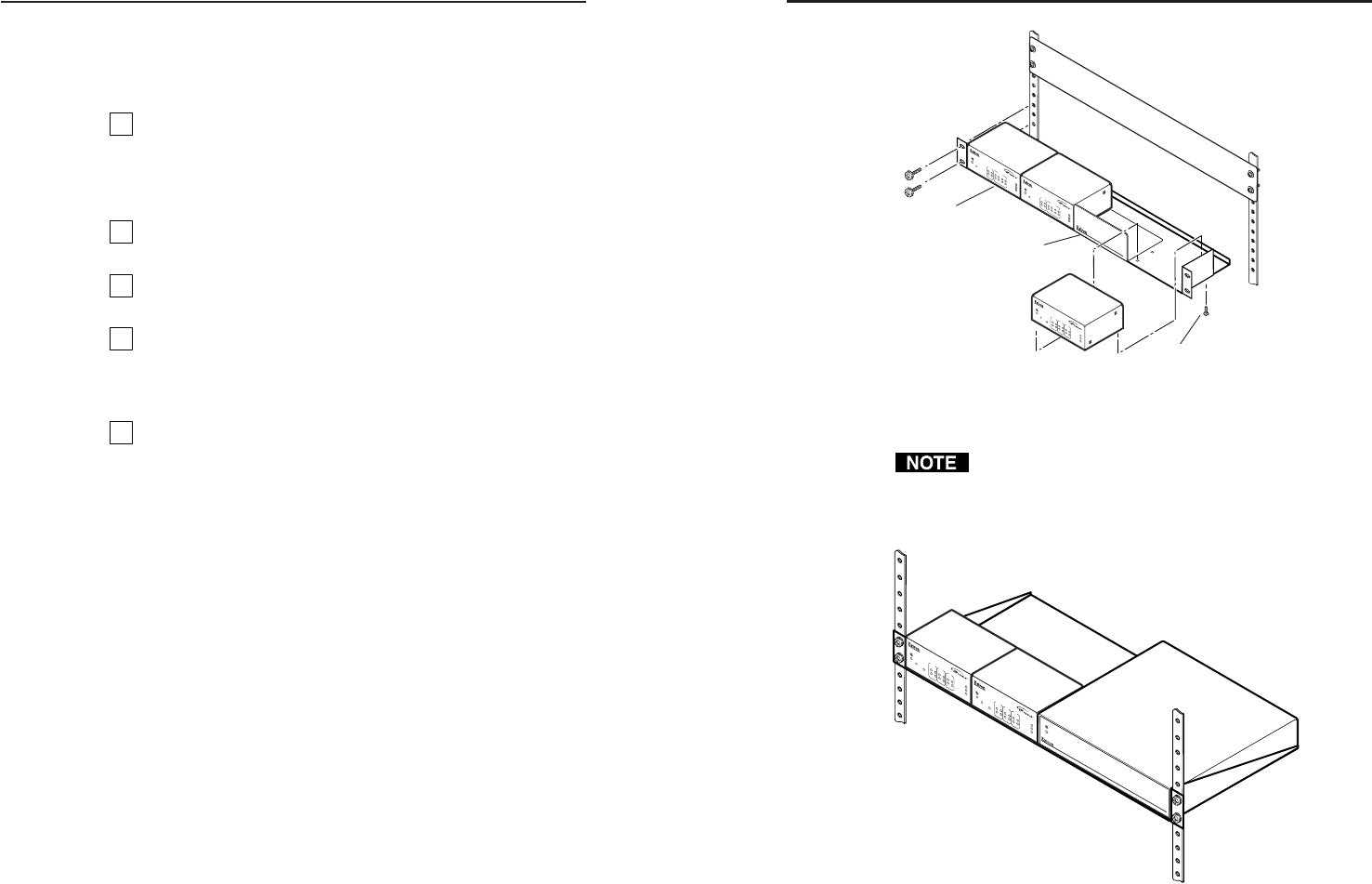
Figure 2-1 — Rack mounting the interface on the
VersaTools shelf (SFI244 model shown)
Only products in the IPTools
™
or VersaTools lines can be
mounted to a VersaTools shelf. Any 1U rack-mountable
Extron product can be mounted on the standard shelf
(Extron part #60-190-01).
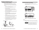
Figure 2-2 — Mounting the interface on the
standard shelf
(2) 4-40 x 3/16" Screws
Use 2 mounting holes on
opposite corners.
1U Rack Shelf
1/4 Rack Width False Front
Face Plate
IPL
T
C
R
4
8
R
4
2
3
1
INPUT
100
LINK
ACT
4
2
3
1
RELAY
8
6
7
5
IPL
T
C
R
4
8
R
4
2
3
1
INPUT
100
LINK
ACT
4
2
3
1
RELA
Y
86
7
5
IP
L
T
S
F
I
2
4
4
1
R
1
0
0
C
O
M
TX
IR
L
IN
K
A
C
T
2
RX
RTS
CTS
2
4
1
3
2
4
I/O
IR
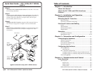
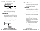
Installation Overview
To install and set up the IPL T SF24 and SFI244 interfaces, follow
these steps:
1
Turn all of the equipment off. Make sure that the video
sources (DSS, cable boxes, or other devices), the IPL
interface, the output devices (monitors, VCRs, projectors,
etc.) and the serial controller are all turned off and
disconnected from the power source.
2
Mount the IPL T unit. See Mounting the IPL T interface
below.
3
Attach the cables. See Connecting the Hardware in
chapter 3.
4
Connect power cords and turn on the devices in the
following order: output devices (projectors, monitors,
speakers), the IPL T unit, a serial controller or computer
(PC), then all input devices (DSS, cable boxes, etc.).
5
Configure the IPL T interface through Telnet, then access
the IPL T interface using an Internet browser.
Mounting the IPL T Interface
Rack mounting
For optional rack mounting, mount the interface on a VersaTools
19" 1U Rack Shelf (Extron part #60-190-20)
(figure 2-1) or a standard Universal 1U Rack Shelf (Extron part
#60-190-01) (figure 2-2). On the standard rack shelf, the
interface mounts in one of four locations to the rear of the rack
or in one of four locations to the front of the rack.
1. If feet were previously installed on the bottom of the IPL T
unit, remove them.
2. Mount the interface on the rack shelf, using two 4-40 x
3/16” screws in opposite (diagonal) corners to secure the
interface to the shelf.
3. Install blank panel(s) or other unit(s) to the rack shelf.
4. Insert the shelf into the rack, aligning the holes in the shelf
with those in the rack.
5. Secure the shelf to the rack using the supplied machine
screws. This shelf can be mounted in the front or in the
rear of the rack.
2-2
MDA SERIES
D
IS
T
R
IB
U
T
IO
N
A
M
P
L
IF
IE
R
IP
L T SFI244
1
R
1
0
0
C
O
M
TX
L
IN
K
A
C
T
2
RX
13
2
4
1
3
2
4
I/O
IR
IP
L T
SFI244
1
R
1
0
0
C
O
M
TX
L
IN
K
A
C
T
2
RX
1
3
2
4
1
3
24
I/O
IR