


IPL T SF24 and IPL T SFI244 • Communication and Control
IPL T SF24 and IPL T SFI244 • Communication and Control
Communication and Control, cont’d
4-5
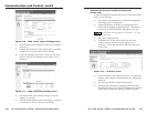
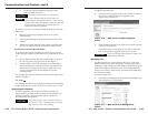
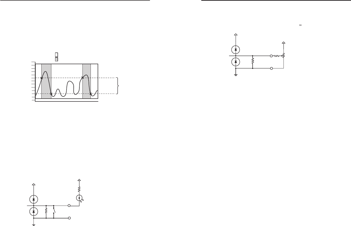
Analog input
When a Flex I/O port is configured as an analog input, the port
can measure 0 to 25.3VDC with 12bit accuracy. A DC level will
be indicated by a count from 0-4096 (
6mv/count).
Figure 4-7 — Sample of an analog input for a
level adjustment, using a 10K pot
Bidirectional serial control interface ports
The IP Tools family of products has several models that
incorporate bidirectional serial control ports. The serial ports
allow for control of a wide variety of existing Extron and third-
party devices. The most common serial control formats are RS-
232, RS-422, and RS-485. Within the IPL T products, there are
two different implementations for the serial control ports: the
9-pin D connector and the captive screw connector.
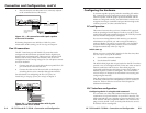
9-pin D Connectors — On some IPL T units, serial control is
accessed through a 9-pin D connector. In this
configuration, all three control formats are available and
fully software configurable. By selecting the RS-232
format, hardware handshaking (RTS, CTS) is also
available. The RS-232 connection uses the same industry
standard interface pin-out as found on standard PCs. If
selecting either RS-422 or RS-485 formats, verify proper
wiring as detailed in figure 2-8. These two formats do not
have an industry standard pin-out and will vary from
device to device.
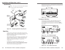
Captive Screw Connectors — On other IPL T units, several of
the serial interface ports are connected on captive screw
terminals. When using the ports on the captive screw
terminals, only RS-232 control is available, and hardware
handshaking is unavailable. Since RS-232 is the most
common control interface encountered, this port
configuration allows for quick termination.
10
+30V
+12V
GND
24K
10K
I/O
4-4
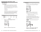
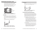
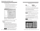
If the integrator selects threshold voltages that are more than
0.1V apart, a deadband, or hysteresis, will be established.
In the example below, the lower threshold voltage is set at
+6VDC and the upper threshold is set at +16VDC. The colored
bands show state changes on the logical outputs.
The range between 6-16VDC is the deadband in which the
signal can fluctuate without affecting the input state.
Figure 4-5 — High and low transitions of
adjustable threshold with deadband (hysteresis)
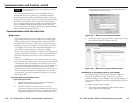
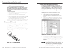
Digital output
When a Flex I/O port is configured as a digital output, it is set
to offer two output states: “On” and “Off”. When the port is set
to an “On” state, (SW1 is closed), the I/O pin is connected to
ground (each I/O port is capable of sinking 250mA max.). When
the port is set to the “Off” state, (SW1 is open), the output pin is
floating.
If the application calls for TTL compatibility, SW2 can be
selected to provide a 2K pull-up resistor to +5VDC.
Figure 4-6 — Sample of a digital output port
driving an LED using an external +5VDC source
2
4
6
8
10
12
14
16
18
20
22
24
26
Low
High
Time
VDC
Upper
Hysteresis
Threshold
Lower
Threshold
I/O
24K SW1
390
+30V
+5V
GND