


Introduction, cont’d
SW AV Series Switcher • Introduction1-4
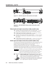
External sync input and output connectors — Allow the switcher to use a black
burst (genlock) signal to synchronize switching during the vertical interval.
This ensures glitch-free switching among multiple timed sources.
Audio switchers
Captive screw connector (A) models
Inputs — These switchers input 4, 6, 8, or 12 balanced or unbalanced stereo audio
signals, on 3.5 mm, 5-pole captive screw terminals.
Outputs — The selected audio input is split, buffered, and output as 2 balanced or
unbalanced audio signals, on 3.5 mm, 5-pole captive screw terminals.
RCA connector (A RCA) models
Inputs — These switchers input 4, 6, 8, or 12 unbalanced stereo audio signals on
left and right RCA connectors.
Outputs — The selected audio input is split, buffered, and output on 2 sets of
connectors.
• One balanced or unbalanced audio signal, on a 3.5 mm, 5-pole captive screw
terminal.
• One unbalanced stereo audio signal on left and right RCA connectors.
All audio models
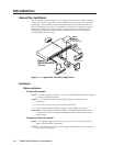
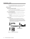
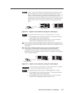
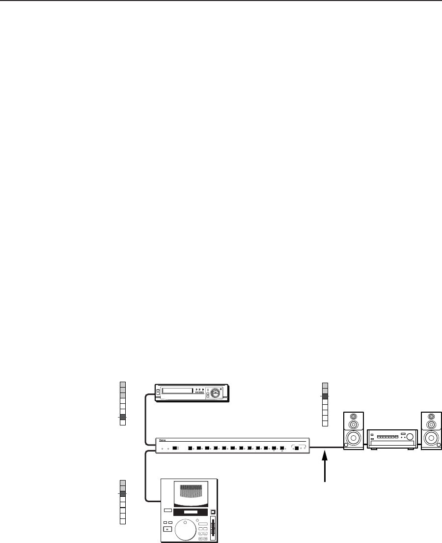
Audio gain/attenuation — Users can set the input level of audio gain or
attenuation (-18 dB to +24 dB) via the RS-232 link or from the front panel.
Individual input audio levels can be adjusted so there are no noticeable
volume differences between sources (figure 1-2) and for the best headroom
and signal-to-noise ratio. This function also eliminates the need for separate
preamps or attenuators when used with professional (higher line level) and
consumer (lower line level) audio equipment.
Audio
Inputs
Audio
Inputs
Consumer VCR
No noticeable volume
differences between sources
Audio System
Pro CD Player
SW AV Series Switcher
+2
-1
-3
-7
-10
-14
Low Audio
Output Level
+5
+8
+4
+1
-2
-5
-8
-12
+7
+10
+2
-1
-4
-7
-10
-14
Output
Level
+5
+8
+4
+1
-2
-5
-8
-12
+7
+10
dBVdBu
High Audio
Output Level
dBVdBu
+2
-1
-3
-7
-10
-14
+5
+8
+4
+1
-2
-5
-8
-12
+7
+10
dBVdBu
SW SERIES
VIDEO / AUDIO SWITCHER
AUDIO
CONF/SAVE
EXECUTIVE
MODE
12
11
10
9
8
7
6
5
4
32
1
AUTO SWITCH
ACTIVE
VIDEO
AUDIO
I/O
-dB
+dB
Figure 1-2 — Audio gain and attenuation