


QS-1SW AV Series Switchers • Quick Start
Quick Start — SW AV Series Switchers
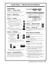
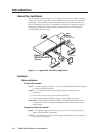
Installation
Step 1 — Power down
Turn off power to the input and output devices,
and remove the power cords from them.
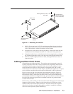
Step 2 — Mounting
If desired, mount the switcher in a rack or under a
table.
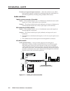
Step 3 — Inputs
As applicable to your switcher, connect:
a Up to 4, 6, 8, or 12 S-video inputs to
the Input connectors.
b Up to 4, 6, 8, or 12 composite video
inputs to the Input connectors.
c Up to 4, 6, 8 or 12 unbalanced stereo
audio inputs to the input RCA
connectors.
d Up to 4, 6, 8 or 12 balanced or
unbalanced stereo audio inputs to
the input captive screw connectors.
Step 4 — Outputs
As applicable to your switcher, connect:
a An S-video display
or other device to
the Output B
connector.
b 1 or 2 composite
video displays or
other devices to the Output connector(s).
c An unbalanced stereo audio device to the
output A connectors.
d 1 or 2 balanced or unbalanced stereo audio
devices to the output connectors.
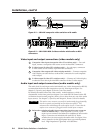
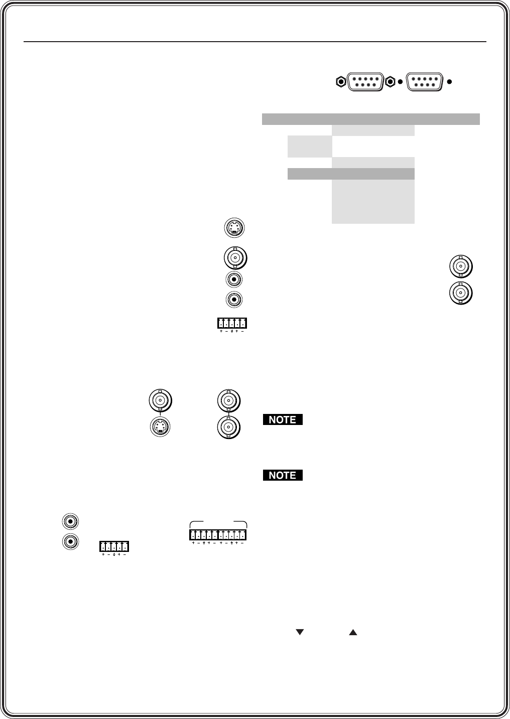
Step 5 — Remote/RS-232
If desired, connect a control system, computer, or
contact closure device (SW 4 and SW 6 models
only) to the Remote (SW 4 and SW 6 models only)/
RS-232 (SW8 and SW12 models only) port.
5, Cont’d
Female
51
96
Male
15
69
— or —
LR
1
— or —
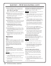
Step 6 — External Sync
If desired, feed a black burst (gen lock)
signal to the external sync connectors.
Step 7 — Power up
Plug the switcher and input and output devices
into a grounded AC source. Turn on the input and
output devices.
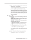
Front Panel Controls
I/O button selects video, audio, or both for input
selection.
The I/O button has no function on audio-
only switchers.
Video and Audio LEDs indicate whether video,
audio, or both are selected.
The Audio LED is always lit on audio-only
switchers.
Input buttons select inputs for output. Input
buttons 1, 2, 3, and 4 also select the switcher
mode.
Input LEDs identify the input selected for output.
Breakaway audio is indicated by a blinking
input LED. The first four input LEDs also
indicate audio gain settings.
Audio configuration/save button and LED enable
the user to view and/or change the current
audio level setting for each input.
Down (
) and Up ( ) buttons and LEDs decrease
or increase the audio level for the selected input
and indicate the decrease and increase.
-dB/+dB LEDs indicate the polarity (- = attenuation,
+ = gain) of the audio level setting.
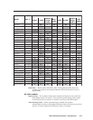
Pin RS-232 Contact closure Function
1 — In#1 * Input #1 *
2TX
—
— Transmit data (-)
3 RX Receive data (+)
4 — In#2 * Input #2 *
5 Gnd Gnd Signal ground
6 — In#3 *
In#4 *
In#5 †
* SW 4 and SW 6 models only
† SW 6 models only
In#6 †
Input #3 *
Input #6 †
Input #4 *
Input #5 †
7—
8—
9—
IN
OUT
A
S-video
Switcher
B
A
B
Composite
Video Switcher
— or —
RCA Connector
Audio Switcher
OUTPUT A
OUTPUT B
LR
L
R
Captive Screw
Audio Switcher
LR
LR
OUTPUTS
A
B
— or —