


2-5SW AV Series Switchers • Installation
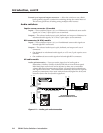
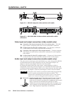
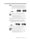
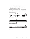
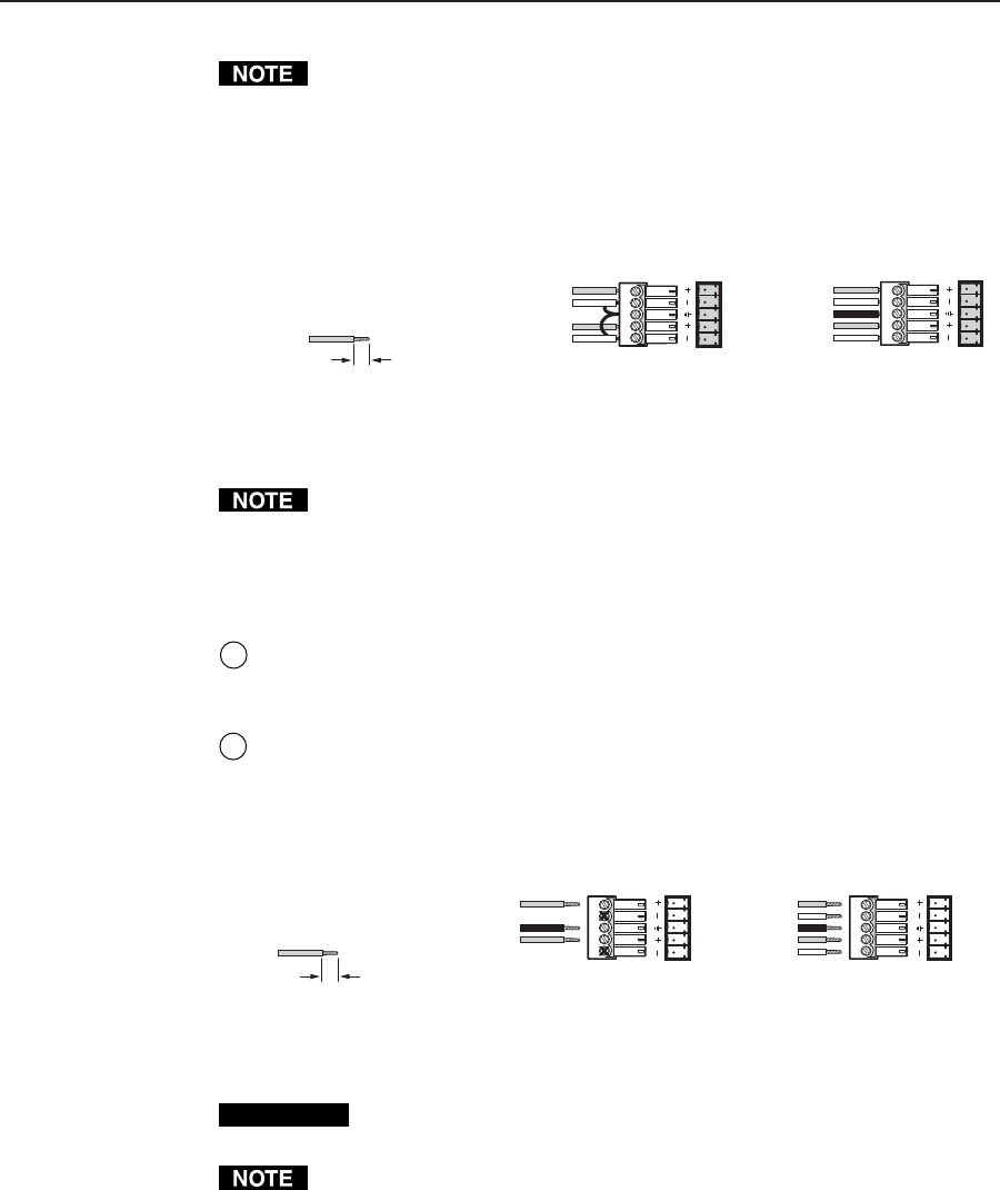
Figure 2-4 shows three methods of wiring the captive screw audio connectors
for input and figure 2-5 shows two methods of wiring the connectors for
output. A mono audio connector consists of the tip and sleeve. A stereo audio
connector consists of the tip, ring and sleeve. If wiring a captive screw
connector from an existing unbalanced audio cable, the white insulated wire is
typically the left channel (tip) and the red insulated wire is typically the right
channel (sleeve). There is no reliable standard for existing balanced audio
cables.
LR
LR
Unbalanced Stereo Input
Tip
Sleeve
Tip
Sleeve
Balanced Stereo Input
Tip
Ring
Sleeve (s)
Tip
Ring
(high impedance)
(high impedance)
0.2” (5 mm) max.
Do not tin the wires!
Figure 2-4 — Captive screw connector wiring for audio inputs
The length of exposed wires is critical. The ideal length is 0.2” (5 mm).
• If the stripped section of wire is longer than 0.2”, the exposed wires may
touch, causing a short cir
cuit between them.
• If the stripped section of wire is shorter than 0.2”, wires can be easily
pulled out even if tightly fastened by the captive screws.
6
RCA connector audio inputs (RCA connector audio (A RCA) models only) —
Each input has a pair (left and right) of RCA connectors for unbalanced stereo
audio input.
7
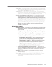
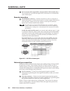
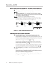
Balanced or unbalanced audio output connectors (all audio models) —
These 3.5 mm, 5-pole captive screw connectors output the selected
unamplified, line level audio. Connect audio devices, such as an audio
amplifier or powered speakers to these connectors. See figure 2-5 to properly
wire an output connector.
0.2” (5 mm) max.
Do not tin the wires!
Unbalanced Stereo Output
Tip
NO GROUND HERE.
Sleeve(s)
Tip
NO GROUND HERE.
Balanced Stereo Output
Tip
Ring
Tip
Ring
LR
LR
Left
Right
Left
Right
Figure 2-5 — Captive screw connector wiring for audio output
CAUTION
Connect the sleeve to ground (Gnd). Connecting the sleeve to a negative
(-) terminal will damage the audio output circuits.
The length of exposed wires is critical. The ideal length is 0.2” (5 mm).
• If the stripped section of wire is longer than 0.2”, the exposed wires may
touch, causing a short circuit between them.
• If the stripped section of wire is shorter than 0.2”, wires can be easily
pulled out even if tightly fastened by the captive screws.