


Installation, cont’d
SW AV Series Switchers • Installation2-6
8
RCA connector audio output (RCA connector audio (A RCA) models only) —
The switcher has a pair (left and right) of RCA connectors for an unbalanced
stereo audio output.
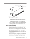
Remote connection
9
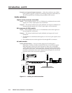
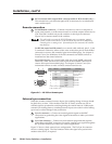
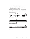
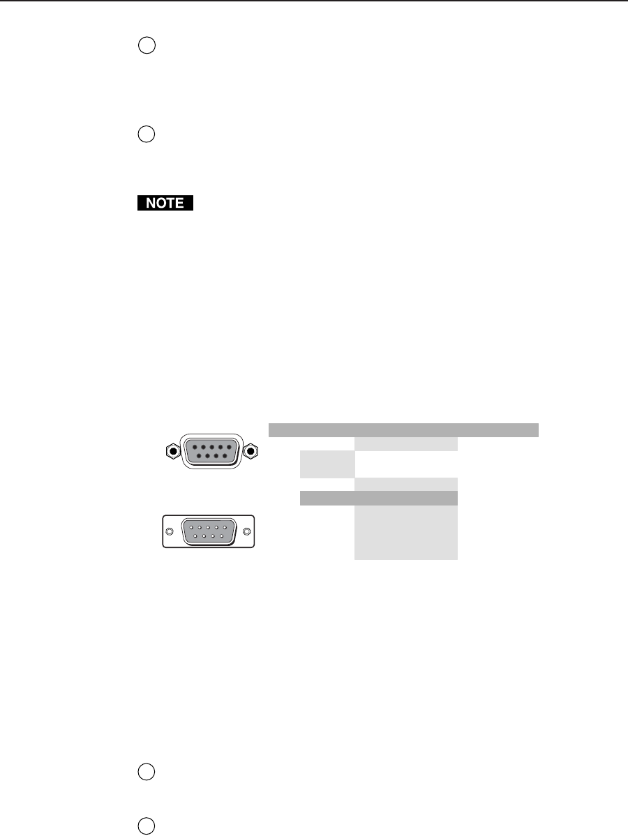
RS-232/Remote connector — Connect a host device, such as a computer or
touch panel control, or an IR remote control or a remote contact closure device
(SW 4 and SW 6 models only) to the switcher via this 9-pin D connector
(figure 2-6) for remote control of the switcher.
The cable used to connect the RS-232/Remote port to a computer, control
system, contact closure device, or IR control kit may need to be modified by
removing pins or cutting wires. If unneeded pins are connected, the switcher
may hang up.
For RS-232 control and IR control, use a control cable with only pins 2, 3, and
5 connected. Otherwise, either cut the wires to the other pins in hard-shelled
connectors or remove the unneeded pins from molded plugs. See chapter 4,
Remote Control, for definitions of the SIS commands and details on how to
install and use the control software.
For contact closure, use a control cable with pins 2 and 3 NOT connected.
Otherwise, either cut the wires to these pins in hard-shelled connectors or
remove these pins from molded plugs. See chapter 4, Remote Control, for
information on how to make a remote contact closure device.
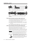
Pin RS-232 Contact closure Function
1 — In#1 * Input #1 *
2TX
—
— Transmit data (-)
3 RX Receive data (+)
4 — In#2 * Input #2 *
5 Gnd Gnd Signal ground
6 — In#3 *
In#4 *
In#5 †
* SW 4 and SW 6 models only
† SW 6 models only
In#6 †
Input #3 *
Input #6 †
Input #4 *
Input #5 †
7—
8—
9—
51
96
Female
5
9
Male
1
6
Figure 2-6 — RS-232 or Remote port
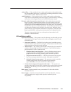
External sync connection
When the switcher switches between inputs, the resulting change in image should
be glitch-free, or clean. Video models of the SW AV Series switcher can use an
external signal to synchronize switching during the vertical interval. Without the
external sync locking feature, switching between inputs can result in a brief rolling
(sync loss) or a brief change in the picture size.
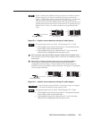
10
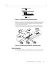
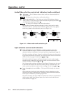
Sync In connector — Connect an external genlock signal to this BNC
connection for genlocking the video signal in broadcast or other sync-critical
applications.
11
Sync Out connector — Connect any downstream equipment that requires
genlocking to this BNC connector to route the external sync signal throughout
the system in broadcast or other sync-critical applications.
Figure 2-7 shows a basic external sync configuration. The Ext Sync In connector
receives a timing signal. The Out connector allows the signal to be passed on to
another video device, if required.