


QS-1TPX 88 Matrix Switcher Quick Start
Quick Start — TPX Matrix Switchers
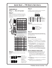
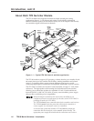
Installation
Step 1 — Turn off power
Step 2
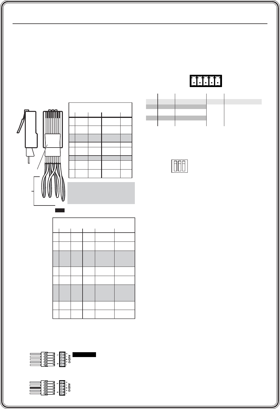
Cable the switcher for twisted pair input and
output. See Termination of TP cable in chapter 2,
Installation, to properly terminate the RJ-45
connectors.
Step 3
TPX 88 A: Cable the switcher for stereo audio
output.
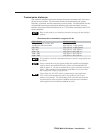
GND
TX-
TX +
RX -
RX +
RS-232 FunctionPin
Gnd
—
TX+
—
RX+
Gnd
TX-
TX+
RX-
RX+
Signal ground
Not used
Transmit data
Not used
Receive data
Gnd
TX-
TX+
RX-
RX+
Signal ground
Transmit data (-)
Transmit data (+)
Receive data (-)
Receive data (+)
RS-422 Function
Unbalanced Output
Tip
See caution
Sleeve
Tip
See caution
Balanced Output
Tip
Ring
Sleeve (s)
Tip
Ring
CAUTION
Connect the
sleeve to ground.
Connecting the
sleeve to a
negative (-)
terminal will
damage the audio
output circuits.
Step 4
If desired, connect a control system or computer
to the Remote (RS-232/RS-422) port.
Step 5
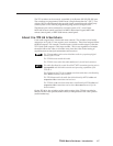
Set the rear panel Remote DIP switches.
Step 6
Plug the switcher and input and output devices
into a grounded AC source, and turn on the input
and output devices.
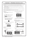
Definitions
Tie — An input-to-output connection.
Set of ties — An input tied to 2 or more outputs.
Configuration — One or more ties or sets of ties.
Current configuration — The currently active
configuration (also called configuration 0).
Global preset — A configuration that has been
stored. One preset can be assigned to each
input button. When a preset is retrieved from
memory, it becomes the current configuration.
Front Panel Controls
Input and output buttons and LEDs select and
identify inputs and outputs. Input buttons
also select presets. On the TPX 88 A, the
input and output LEDs also display the audio
levels.
Enter button saves changes when you change the
configuration.
Preset button saves a configuration as a preset or
recalls a previously-defined preset.
RS-232
Switches 1 & 2 down,
3 up for RS-422.
All switches up
for RS-232. (Default.)
RS-422
Clip Down
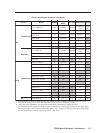
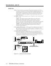
TP/VTT transmitters and receivers
Side
1
1&2
3&6 4&5
2345678
12345678
Pin color
RGBHV/
audio
Video/
audio
1
White-
green
Red/
V. sync+
Video+
2 Green
Red/
V. sync-
Video-
3*
White-
orange
Audio+
4 Blue Blue Green+ N/C
5
White-
blue
White-
blue
Green- N/C
6* Orange Green Audio-
N/C
N/C
7
White-
brown
Blue/
H. sync+
Audio+
8Brown
Blue/
H. sync-
Audio-
RJ-45
connector
Twisted
Pairs
568 A
color
568 B
White-
orange
Orange
White-
green
White-
brown
Brown
7&8
* The TPX 88 A switches pair 3 and 6.
The TPX 88 does not switch pair 3 and 6.
Audio or serial data from an RGB video MTP
is incompatible with both TPX models.
They cannot be switched.
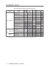
MTP transmitters and receivers
Pin
1
Video +
2 Video –
3*
4
Audio
left +
5
Audio
left –
6*
NONE
NONE
NONE
NONE
7
Audio
right +
8
Audio
right –
Color
White-
green
Green
White-
orange
Blue
White-
blue
Orange
White-
brown
Brown
Color
568 A 568 B
Video
MTP
White-
orange
Orange
White-
green
Blue
White-
blue
Green
White-
brown
Brown
If you are using Enhanced Skew-Free™ A/V cable,
use the TIA/EIA T 568A standard only.
NOTE
Chroma (C)
& audio left +
Chroma (C)
& audio left –
A
udio right+
Audio right –
S-video
MTP
Red/
V. Sync +
Red/
V. Sync –
Mono audio +
or RS-232 +
(MTP 15HD
only)
Green +
Green –
Mono audio –
or RS-232 –
(MTP 15HD
only)
Blue/
H. Sync +
Blue
H. Sync –
RGB video
MTP
Luma (Y) +
Luma (Y) –