


Programmer’s Guide, cont’d
TPX 88 Matrix Switchers • Programmer’s Guide4-4
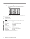
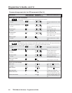
Using the Command/Response Table
The command/response table begins on page 4-5. Lower case letters are acceptable
in the command field except where indicated for the gain and attenuation
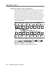
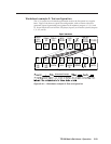
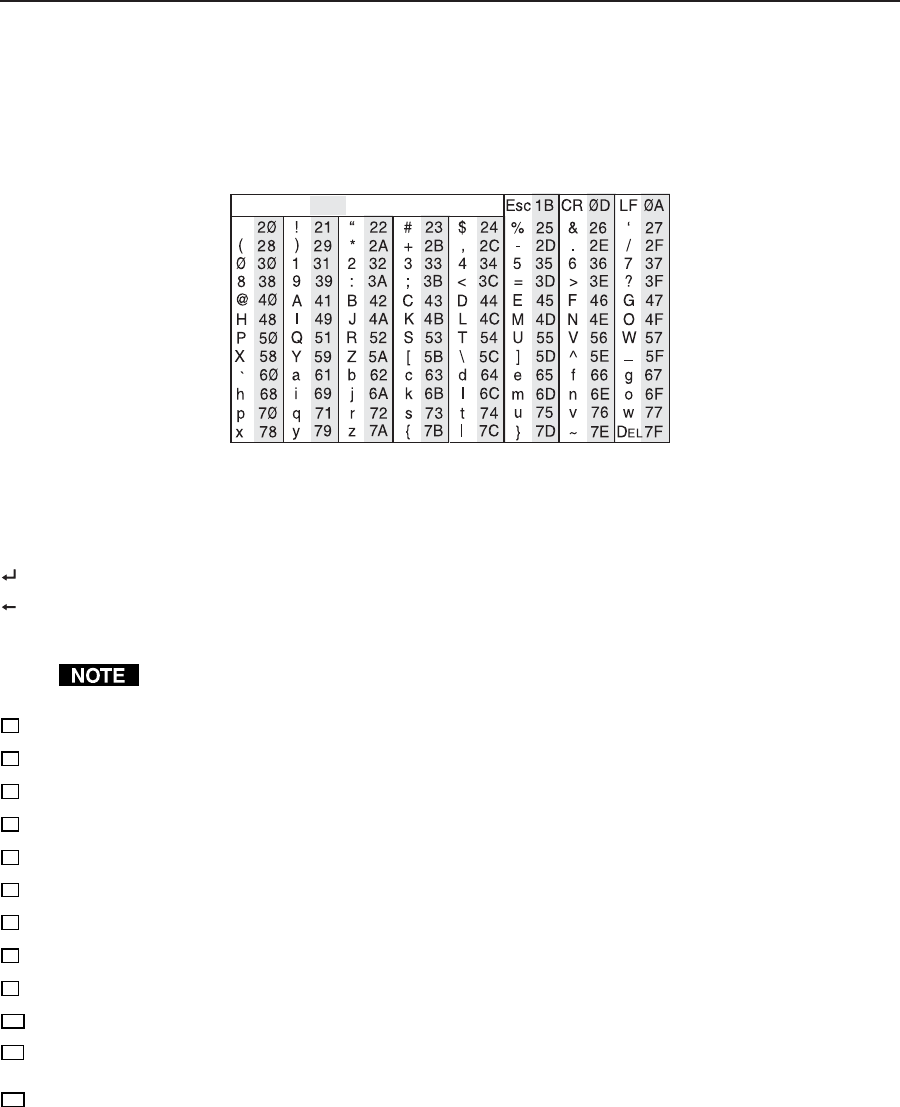
commands. The table below shows the hexadecimal equivalent of each ASCII
command.
ASCII to HEX Conversion Table
Space
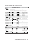
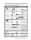
Symbols are used throughout the table to represent variables in the command/
response fields. Command and response examples are shown throughout the table.
Symbol Definitions:
= Carriage return/line feed
= Carriage return (no line feed)
• = Space
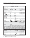
Input and output numbers in commands may be entered as either 1-digit, 2-digit, or 3-digit
numbers. All input and output numbers are reported as 2-digit numbers in the response.
X1
= Input number 01 – 08
X2
= Input number (for tie) 00 – 08 (0=disconnected)
X3
= Output number 01 – 08
X4
= Numeric dB value -18 to +24 (43 steps of gain or attenuation)
X5
= Audio gain 0 – 24 (1 dB/step)
X6
= Audio attenuation 1 – 18 (1 dB/step)
X7
= Volume adjustment range 0% to 100%
X8
= Mute, executive mode 0 = off, 1 = on
X9
= Group # (for I/O grouping) 1 through 4 groups (0 = no group)
X10
= Global preset # 16 maximum (0 = current configuration)
X11
= Video/audio mute: 0 = no mutes
2 = audio mute
X12
= Controller firmware version number to second decimal place