


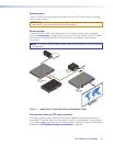
c
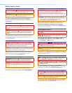
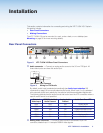
HDMI connectors — Connect a digital video source device to either or both female
HDMI connectors, labeled inputs 2 and 3. They can accept HDMI, DVI, or dual mode
DisplayPort video sources.
d
XTP connector — Connect a twisted pair cable to the RJ-45 connector labeled
XTP Out and the XTP input port on another XTP device to pass all signals (see
TP Cable Termination and Recommendations on page 6). This cable carries the
following signals:
• Digital video
• Digital audio
• Bidirectional RS-232 and IR commands
• Remote power
• Ethernet communication
• System communication
Link LED indicator — Lights yellow when XTP devices are connected and
communication is established.
Signal LED indicator — Lights green when the transmitter outputs a video signal or a
test pattern.
ATTENTION:
• Do not connect this connector to a computer data or telecommunications
network.
• XTP remote power is intended for indoor use only. No part of the network that
uses XTP remote power should be routed outdoors (see Remote power on
page 9).
e
LAN connector — Connect a control device or device to be controlled to this LAN
connector for 10/100 Ethernet communication through this pass-through port. LEDs on
this connector indicate link and activity status.
f
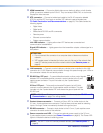
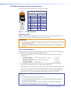
RS-232 Over XTP port — To pass bidirectional serial or other control signals
between XTP-compatible devices, connect a control device to the 5-pole
captive screw connector. The port includes only the 3 poles labeled
“RS-232.”
IR Over XTP port — To transmit and receive IR signals (up to 40 kHz),
connect a control device to the 5-pole captive screw connector. This port
includes only the 2 poles labeled “IR” and shares the ground pole with the
RS-232 port.
NOTE: RS-232 and IR data can be transmitted simultaneously (see RS-232 and IR
Communication on page 7 for wiring details).
g
Contact closure connector — Connect an Extron KP 6 or similar device to the
3.5 mm, 4-pole captive screw connector. The first three ports are used for selecting
inputs 1 through 3 when momentarily shorted to the ground port.
h
RS-232 connector — Connect a host device to the 3.5 mm, 3-pole captive screw
connector for serial control of the switcher.
i
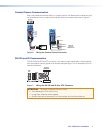
Power connector and LED — Connect an external power supply to the 3.5 mm,
2-pole captive screw connector (see Power Connection on page 8). The Power LED
lights to indicate the device is receiving power.
NOTE: The XTP T USW 103 can be powered remotely (see Remote power on
page 9).
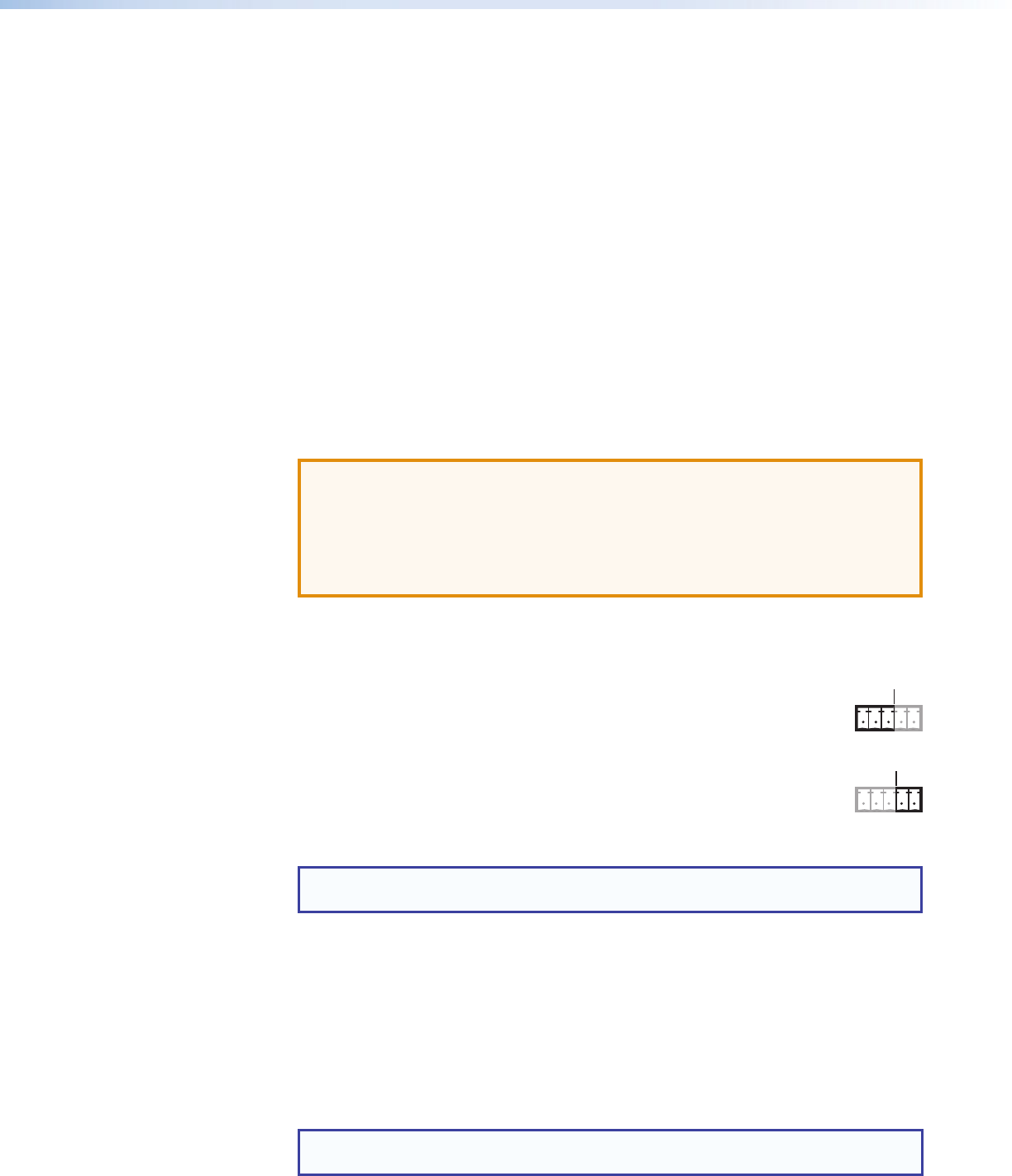
IR
Tx Rx G Tx Rx
RS-232
IR
Tx Rx G Tx Rx
RS-232
XTP T USW 103 • Installation 4