


Operation
This section describes the front panel features and operations of the XTP T USW 103.
Topics in this section include:
• Front Panel Features
• Front Panel Operation
Front Panel Features
HDCP
SIGNAL
AUDIO
SIGNAL CLIP
AUTO
SWITCH
XTP T USW 103
CONFIG
1
2
3
1
2
3
STATUS
MODE
NORMAL
AUTO
a
c
d
b
e
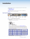
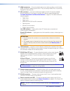
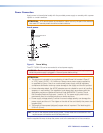
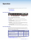
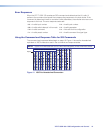
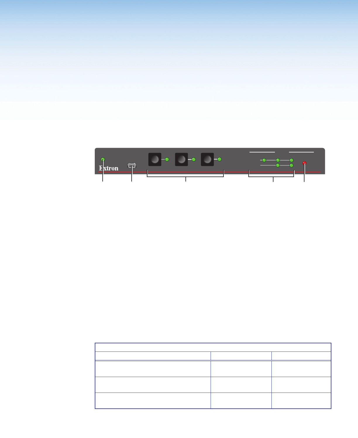
Figure 10. XTP T USW 103 Front Panel Features
a
Auto Switch LED — Lights when the transmitter is in auto switch mode.
b
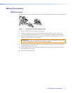
Config port — Connect a host device to the front panel mini USB B Config port.
c
Input selection buttons — Select inputs 1 through 3 or modes of operation. The
corresponding LEDs light to indicate the active input.
d
Status LEDs — The Signal LEDs light to indicate the signal presence of each input.
The HDCP LEDs light when the signal on the corresponding input is HDCP-compliant.
Input 1 (the VGA connector) does not have an HDCP LED.
e
Audio Signal Clip LED — Lights when the analog audio input signal is -3 dBFS or
above. The light remains lit for 200 ms after the audio input signal drops below -3 dBFS.
Front Panel Operation
The input selection buttons are used to manually select inputs 1 through 3 or enable and
disable device modes. The LEDs indicate status and provide feedback of the currently
selected input. Press and hold the input selection buttons in the combinations shown in the
table below to enable or disable device modes.
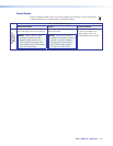
Front Panel Button Combinations for Device Modes
Mode Button Combination Indicator Response
Executive (disabled by default) 1, 2, and 3 All front panel LEDs
blink 3 times.
Auto switch (prioritize the highest numbered
active input)
1 and 3 Auto Switch LED
lights.
Normal switch (default switch mode) 1 and 2 Auto Switch LED
turns off.
Front panel operations can also be performed remotely with SIS commands (see SIS
Configuration and Control on page 13) or the XTP Configuration Software
(see XTP System Configuration Software on page 20).
10XTP T USW 103 • Operation