CONNECTIONS
System control connections
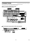
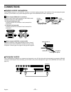
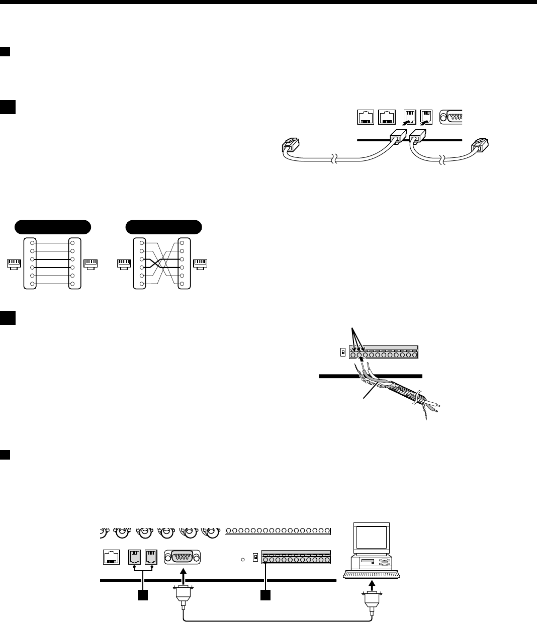
Use the RS485 connector or the CONTROL connector to connect a system controller to the multiplexer. After connecting the system
controller, you will need to carry out the settings that are given in the CONTROL SET menu. (See page 72.)
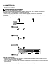
A When using the RS485 (RJ-11) connector
Connect modular cables (sold separately) to the RS485 control
connectors at the rear of the multiplexer.
• If using a straight-type cable
Connect connector A to connector A and connector B to
connector B.
• If using a cross-type cable
Connect connector A to connector B and connector B to
connector A.
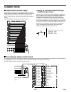
B When using the CONTROL connector (A/B)
Connect a twisted-pair cable (sold separately) to the A, B and C
(ground) terminals of the CONTROL connector at the rear of the
multiplexer. Connect signal A to signal A and signal B to signal B.
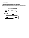
Computer control
When connecting the multiplexer to a computer (sold separately), use a D-Sub 9-pin cable (sold separately) to connect the RS-232C
connector to the computer. After connecting, you will need to carry out the settings that are given in the CONTROL SET menu. (See
page 72.)
61616116
1
2
3
4
5
6
1
2
3
4
5
6
Spare
Spare
Spare
Spare
1
2
3
4
5
6
Spare
Spare
Spare
Spare
1
2
3
4
5
6
Straight type Cross type
To other
connector A
To other
connector A
Straight-type cable Cross-type cable
Push the cable in.
Twisted-pair cable
Ground
To signal A
To signal B
Computer
A B
English
– 11 –


