


List of Figures
ETERNUS DX80 S2/DX90 S2 Disk storage system User’s Guide -Site Planning-
Copyright 2013 FUJITSU LIMITED P3AM-4822-12ENZ0
9
Figure 3.11 iSCSI connection for remote copy (using lines)............................................................................................ 53
Figure 3.12 Example of a LAN connection...................................................................................................................... 55
Figure 3.13 Dual-line power supply when connecting to power sockets......................................................................... 57
Figure 3.14 Dual-line power supply when connecting to UPS units................................................................................ 57
Figure 3.15 Single-line power supply when connecting to power sockets ...................................................................... 57
Figure 3.16 Single-line power supply when connecting to a UPS unit............................................................................ 58
Figure 3.17 Single-line power supply when connecting to a power socket and a UPS unit............................................. 58
Figure 3.18 Power control using a power synchronized unit (when connecting one or two servers) .............................. 61
Figure 3.19 Power control using a power synchronized unit (when connecting three or more servers) ......................... 62
Figure 4.1 AC cable connection .................................................................................................................................... 65
Figure 4.2 QSFP cable connection (single-controller type)........................................................................................... 66
Figure 4.3 QSFP cable connection (dual-controller type).............................................................................................. 67
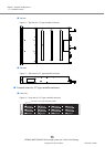
Figure 4.4 Unit installation area .................................................................................................................................. 68
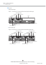
Figure 4.5 Installation diagram for a host interface (single-controller type)................................................................ 70
Figure 4.6 Installation diagram for host interfaces (dual-controller type).................................................................... 71
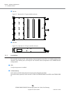
Figure 4.7 Installation diagram for 2.5" drives ............................................................................................................. 74
Figure 4.8 Installation diagram for 3.5" drives ............................................................................................................. 76
Figure 4.9 Drive installation example at shipment (2.5" type controller enclosure)..................................................... 77
Figure 4.10 Drive installation example at shipment (3.5" type controller enclosure)..................................................... 78