Appendix A Mapping Device Path Names 93
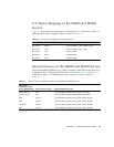
I/O Device Mapping on the M4000 and M5000
Servers
TABLE A-3 shows the device mapping on a midrange server. In the device path, x is
LSB-dependent, and is assigned a value as shown in
TABLE A-2.
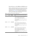
Internal Devices on the M4000 and M5000 Servers
The internal M4000/M5000 devices, which are located at the XSB location 00-0 or 01-
0 (regardless of Uni-XSB or Quad-XSB mode), are shown in
TABLE A-4 and TABLE A-5.
In the device path, x is LSB-dependent, and is assigned a value as shown in
TABLE A-2.
TABLE A-3 I/O Device Mapping on a Midrange Server
Slot Host Bus Adapter Slot Type OpenBoot PROM Device Path
IOU Slot 0 PCI-X /pci@x0,600000/pci@0/pci@8/pci@0,1
IOU Slot 1 PCIe /pci@x0,600000/pci@0/pci@9
IOU Slot 2 PCIe /pci@x1,700000
IOU Slot 3 PCIe /pci@x2,600000
IOU Slot 4 PCIe /pci@x3,700000
TABLE A-4 Internal Devices and Device Paths on the M4000 and M5000 Servers
XSB 00-0/IOU
0 Accessible Internal
Devices (M4000/M5000) Device Physical Location OpenBoot PROM Device Path
Network Port 0 IOU /pci@x0,600000/pci@0/pci@8/pci@0/network@2
Network Port 1 IOU /pci@x0,600000/pci@0/pci@8/pci@0/network@2,1
HD0 System /pci@x0,600000/pci@0/pci@8/pci@0/scsi@1/disk@0
HD1 System /pci@x0,600000/pci@0/pci@8/pci@0/scsi@1/disk@1
CD/DVD System /pci@x0,600000/pci@0/pci@8/pci@0/scsi@1/disk@3
DAT System /pci@x0,600000/pci@0/pci@8/pci@0/scsi@1/tape@2


