


SK-91F467-FLEXRAY V1.1
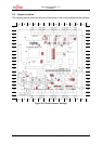
Jumpers and Switches
FMEMCU-UG-910017-11 - 22 - © Fujitsu Microelectronics Europe GmbH
3.4 Power Supply
There are four on-board switching regulators to provide the voltages 5V, 3.3V, 2.5V and
1.8V on the starter-kit. With the power ON/OFF-switch S8 or S9 (S9 is a soldering option to
use a different switch), the main input voltage from DC-connector X5 will be connected to the
VIN voltage of the board. The VIN voltage supplies the switching regulators and the VBat
voltage of the FlexRay physical layer driver modules from TZM (FT1080), if they are
connected to X3 and X7.
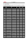
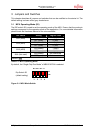
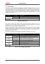
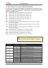
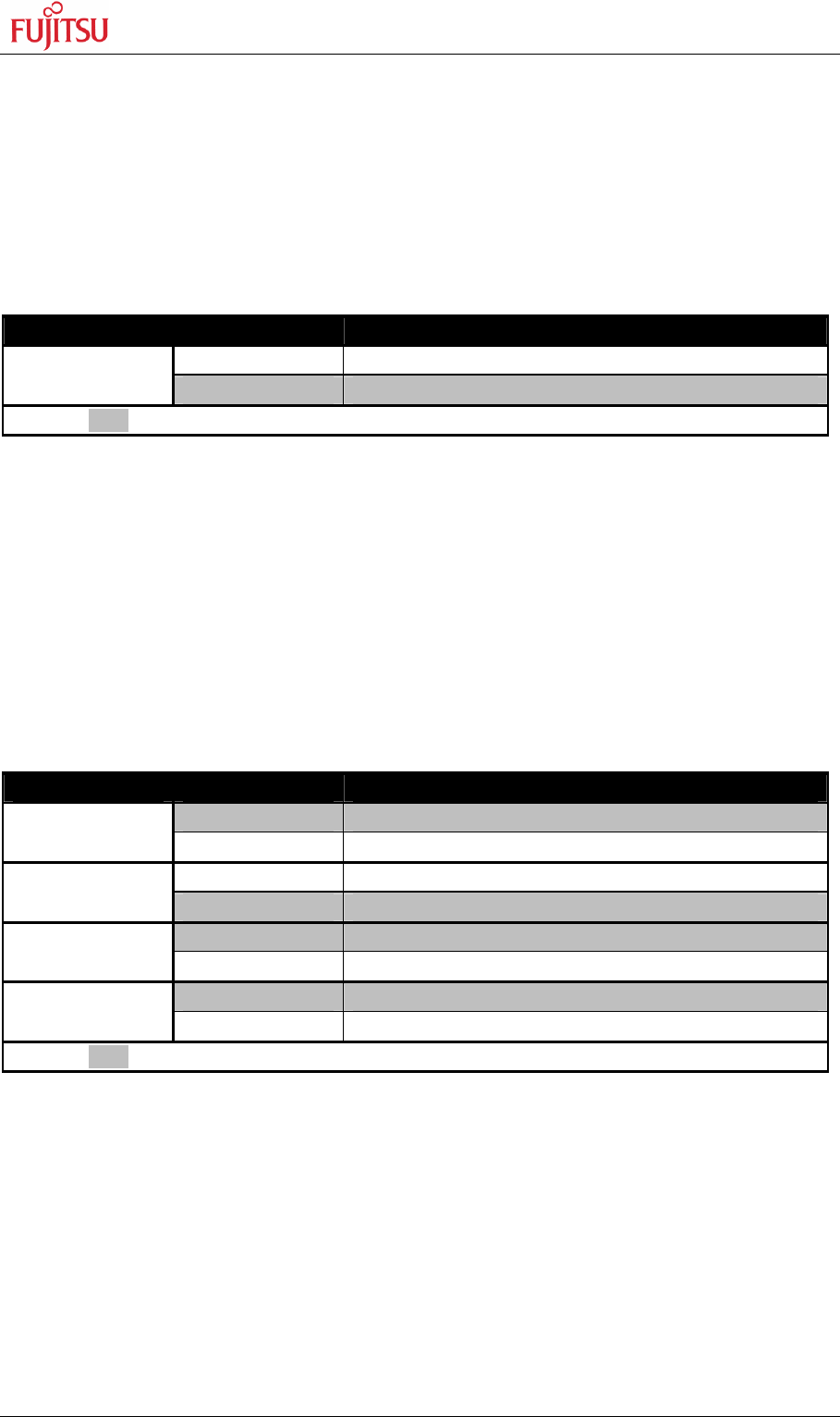
Switch Setting Description
ON (1-2) Power ON
S8 or S9
OFF (2-3) Power OFF
Default: grey
Table 3-4: Power Switch
With JP91 the pins B14, B15 and B16 of the external bus interface connector X14 can be
connected to the VIN voltage, so that it is possible to supply the board from an external
connected board e.g. the Fujitsu FlexRay FPGA board.
There is a triple supply monitor on-board, which monitors three of the four DC output
voltages and generates a system reset, in case with wrong levels of the on board voltages.
5V and 3.3V are always monitored and the third monitored voltage can be selected with the
solder jumpers JP42 and JP43.
With JP68 it is possible to select the whole board supply voltage Vcc to 5V or 3.3V
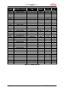
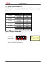
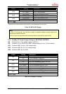
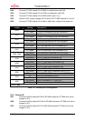
Jumper Setting Description
ON (closed) Vin connected to X14 pins B14, B15 and B16
JP91
OFF (open) Vin not connected to X14 pins B14, B15 and B16
ON (closed) Vcc1V8 connected to supply monitor
JP42
OFF (open) Vcc1V8 not connected to supply monitor
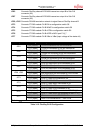
ON (closed) Vcc2V5 connected to supply monitor
JP43
OFF (open) Vcc2V5 not connected to supply monitor
1-2 Vcc is connected to 5V
JP68
2-3 Vcc is connected to 3.3V
Default: grey
Table 3-5: Power supply configurations