


SK-91F467-FLEXRAY V1.1
Jumpers and Switches
© Fujitsu Microelectronics Europe GmbH - 27 - FMEMCU-UG-910017-11
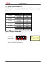
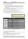
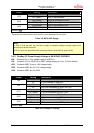
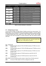
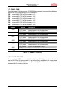
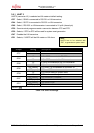
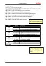
Jumper Setting Description
2-3 CC SPI-mode switch S1-3 connected to CC MDS2
1-2 MCU D25 connected to CC AD1 / AD9
J
P11
2-3 CC SPI-mode switch S1-2 connected to CC MDS1
1-2 MCU D24 connected to CC AD0 / AD8
JP12
2-3 CC SPI-mode switch S1-1 connected to CC MDS0
1-2 MCU D21 connected to CC AD5
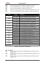
JP14
2-3 MCU INT6 connected to CC INT2
1-2 MCU D20 connected to CC AD4
JP17
2-3 MCU INT7 connected to CC INT3
1-2 MCU CSX3 connected to CC CS
JP19
2-3 MCU CSX6 connected to CC CS
1-2 MCU INT6 connected to CC INT2
JP20
2-3 MCU ASX connected to CC ALE
Default: grey
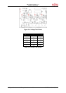
Table 3-10: MCU-FlexRay CC Connection
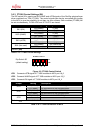
3.6 FlexRay Physical Layer
The SK-91F467-FLEXRAY provides different FlexRay physical layer communication. The
default setting is for RS-485 physical layer communication (on board). To test the original
FlexRay physical layer transceiver, it is possible to deselect the RS-485 transceiver and plug
in FlexRay physical layer driver module from TZM (FT1080). With the TZM (FT1080)
modules the user has the possibility to evaluate transceiver chips from different vendors
quite easy.
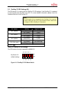
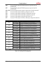
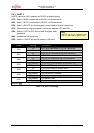
3.6.1 Channel A
JP35 Connects FlexRay channel A RxD to RS-485 transceiver (FT1080 must not be
plugged in X3!)
JP40 Connects FlexRay channel A TxEN to RS-485 transceiver (FT1080 must not be
plugged in X3!)
JP45 Connects FlexRay channel A TxD to RS-485 transceiver (FT1080 must not be
plugged in X3!)
JP38 Connects FlexRay channel A RS-485 transceiver output B to Sub-D-9
connector (X2)
JP41 Connects FlexRay channel A RS-485 transceiver output A to Sub-D-9
connector (X2)
JP34, JP36 Connects RS-485 termination network to signal lines at FlexRay channel A
JP48 Connects FT1080 module CH-A EN to configuration switch S6
Note:
Disconnect the RS-485 physical layer transceiver signals before
plugging in the FT1080 modules to X3 and X7.