


SK-91F467-FLEXRAY V1.1
Connectors
FMEMCU-UG-910017-11 - 38 - © Fujitsu Microelectronics Europe GmbH
4 Connectors
4.1 Power Connector (X5)
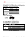
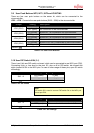
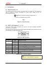
The following figure shows the power connection jack of the starter kit. This connector is
used to connect an external unregulated DC power supply voltage (9V-12V DC
recommended 2000mA).
Table
Figure 4-1: Power Connector
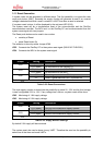
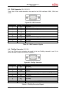
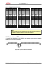
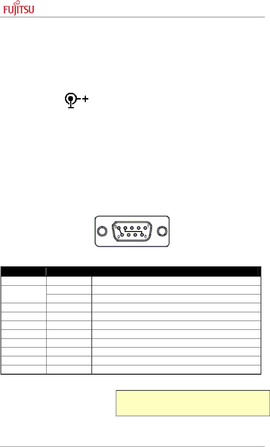
4.2 UART / LIN Connector (X1, X4, X8)
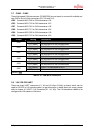
Three 9-pin D-Sub female connectors are used for the serial interfaces LIN/UART2,
LIN/UART4 and LIN/UART5.
Take care, that the RS232 as well as the LIN signals are shared at the connectors and have
to be selected by jumpers (see chapter 3.8).
Figure 4-2: UART Connector
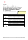
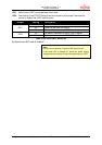
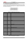
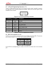
Pin Number Pin Signal Description
1 +VBat Power from LIN bus
TXD RS-232 transmit output
2
LIN Bi-directional LIN-interface
3 RXD RS-232 receive input
4 DTR Connected to DSR (pin 6)
5 GND Ground normally used for RS232 connection
6 DSR Connected to DTR (pin 4)
7 RTS Can be connected with CTS by jumper
8 CTS Can be connected with RTS by jumper
9 LGND Ground normally used for LIN connection
Shield GND Ground
Table 4-1: UART Connector Signals
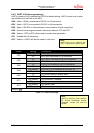
Note:
Please use 1:1 cable for RS232 PC-connection.
Shield is connected to positive voltage supply (+)
Centre is connected to ground (GND)