


SK-91F467-FLEXRAY V1.1
Connectors
FMEMCU-UG-910017-11 - 40 - © Fujitsu Microelectronics Europe GmbH
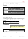
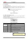
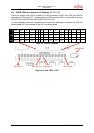
4.5 FlexRay Physical Layer Module Connector (X3, X7)
To use the FlexRay physical layer driver module from TZM (FT1080) there are two special
connectors on board of SK-91F467-FLEXRAY, both for FlexRay channels A and B, to insert
the modules. If the modules FT1080 should be used, it is necessary to disable the RS-485
driver modules (see chapter 3.6).
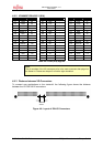
Figure 4-5: FlexRay Physical Layer Connector
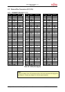
Pin Number Pin Signal Description
1 SGND Signal Ground
2 Shield FlexRay bus shield (filtered)
3 NC Not used
4 BM Bus line Minus
5 NC Not used
6 BP Bus line Plus
7 EN Mode control input
8 NC Not used
9 WAKE Local wakeup
10 NC Not used
11 nSTB Mode control input
12 NC Not used
13 BGE Bus guardian enable
14 NC Not used
15 No Pin Coded
16 No Pin Coded
17 TxD Transmission data input
18 Ubuffer Transmitter supply voltage buffering
19 TxEN Transmission data enable
20 GND Ground
21 RxD Receive data output
22 VIO I/O supply voltage
23 RxEN Receive data enable output (not used)
24 GND Ground
25 INH2 Inhibit switch floating in standby / sleep mode
26 Vcc Supply voltage
27 INH1 Inhibit switch floating in sleep mode
28 GND Ground
29 nERR Error indication
30 VBat Battery supply voltage
31 NC Not used
32 GND Ground
33 NC Not used
34 nCS ID-EEPROM SPI-nCS (connected to optional pin header)
35 NC Not used
36 SDI ID-EEPROM SPI data in (connected to optional pin header)
37 TRXD0 Star (connected to optional pin header)
38 SDO ID-EEPROM SPI data out (connected to optional pin header)
39 TRXD1 Star (connected to optional pin header)
40 SCK ID-EEPROM SPI clock (connected to optional pin header)
Table 4-4: FlexRay Physical Layer Modules