


SK-91F467-FLEXRAY V1.1
Getting Started
FMEMCU-UG-910017-11 - 60 - © Fujitsu Microelectronics Europe GmbH
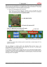
Always check the Linker Settings (“Project – Setup Project – Linker – Disposition”) to make
sure the following memory map is applied according to the project configuration:
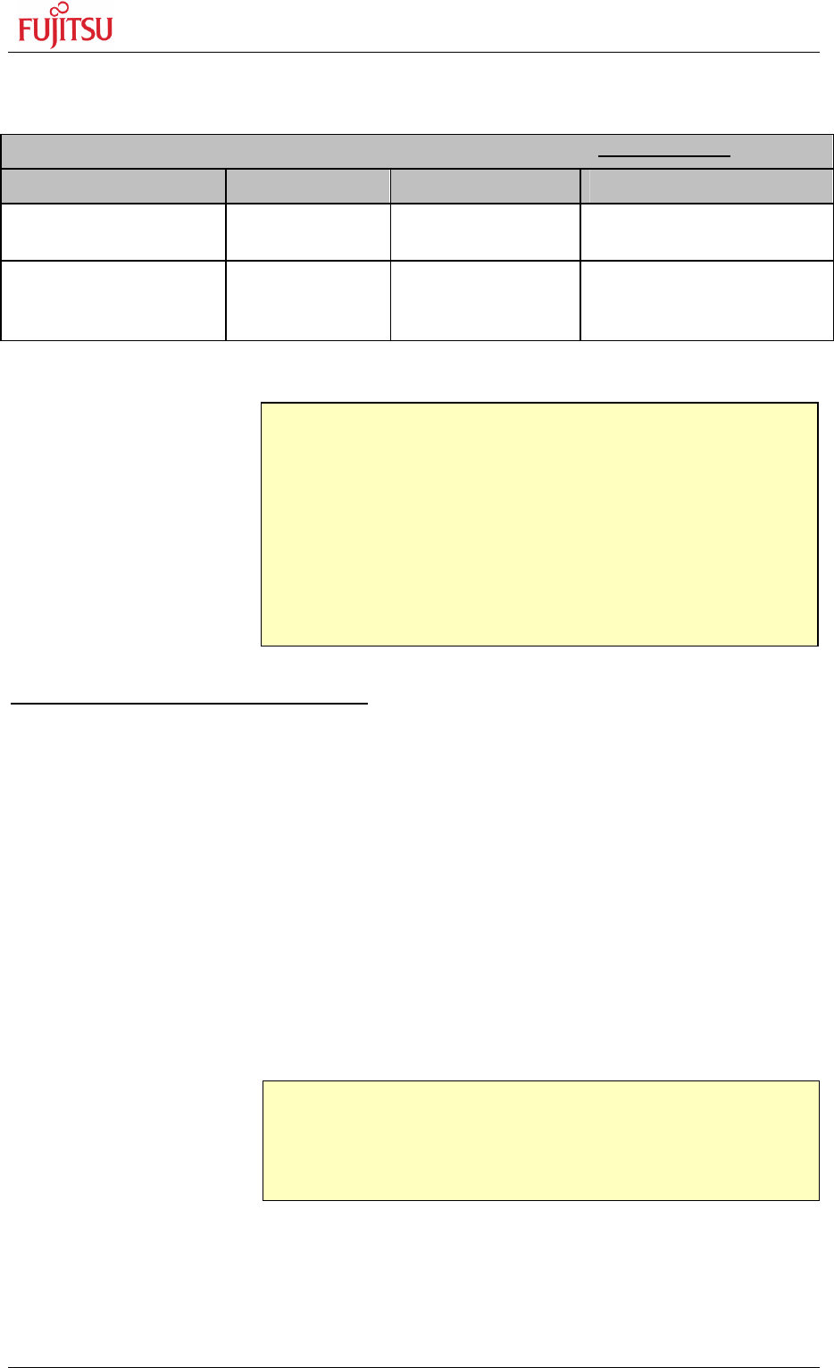
Recommended linker settings for “SK-91F467-xxx” starter kits for debugging
Memory Type Used for Area(s) Sections
Data RAM, Variables, Stack 0x029000 -
0x02FFFF
DATA, INIT, STACK
External SRAM 1MB Code, Const,
IRQ Vector
Table
0x00840000 -
0x0094FFFF
CODE, CONST
Table 5-2: Linker Settings for MB91F467DA Monitor Debugger configuration
Checklist for project configuration:
• Make sure, the correct Target MCU (“Project – Setup Project - MCU” menu)
MB91F467D is selected.
• Use the correct linker settings as outlined above depending on your target
MCU and the target area (embedded flash or external RAM).
• Use the provided templates to make sure the sections are located correctly.
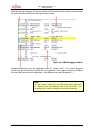
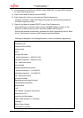
• Always check the *.mp1 file (use right mouse click on top *.abs file in the
project window of Softune Workbench and select “open list file”) to see the
used sections and address areas!
• The following Chip select areas are used by the Softune monitor debugger and
must not be used or overlap with other chip select areas:
CS1 – SRAM 0x0080.0000 - 0x009F.FFFF
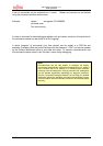
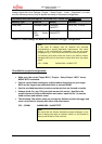
Note:
In any case all settings must be checked and corrected
corresponding to specific application requirements. Also check
settings in the start91467.asm initialisation file! Use the linker
mapping list (e.g. *.mp1 file) to check the final memory allocation.
The following chip select areas are used by the Softune monitor
debugger and must not be used or overlap with other chip select
areas:
CS1 – SRAM 0x0080.0000 - 0x009F.FFFF
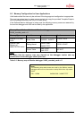
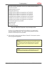
Note:
Be aware that the Softune Workbench monitor debugger is only
able to debug code which is located in RAM! It is not possible to
debug code located in Flash memory!