


SK-91F467-FLEXRAY V1.1
Jumpers and Switches
© Fujitsu Microelectronics Europe GmbH - 35 - FMEMCU-UG-910017-11
3.9 User Push Buttons INT0, INT1, INT2 and ICU0/TIN0
There are four user push buttons on the starter kit, which can be connected to the
microcontroller.
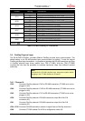
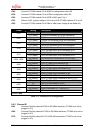
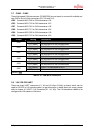
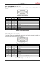
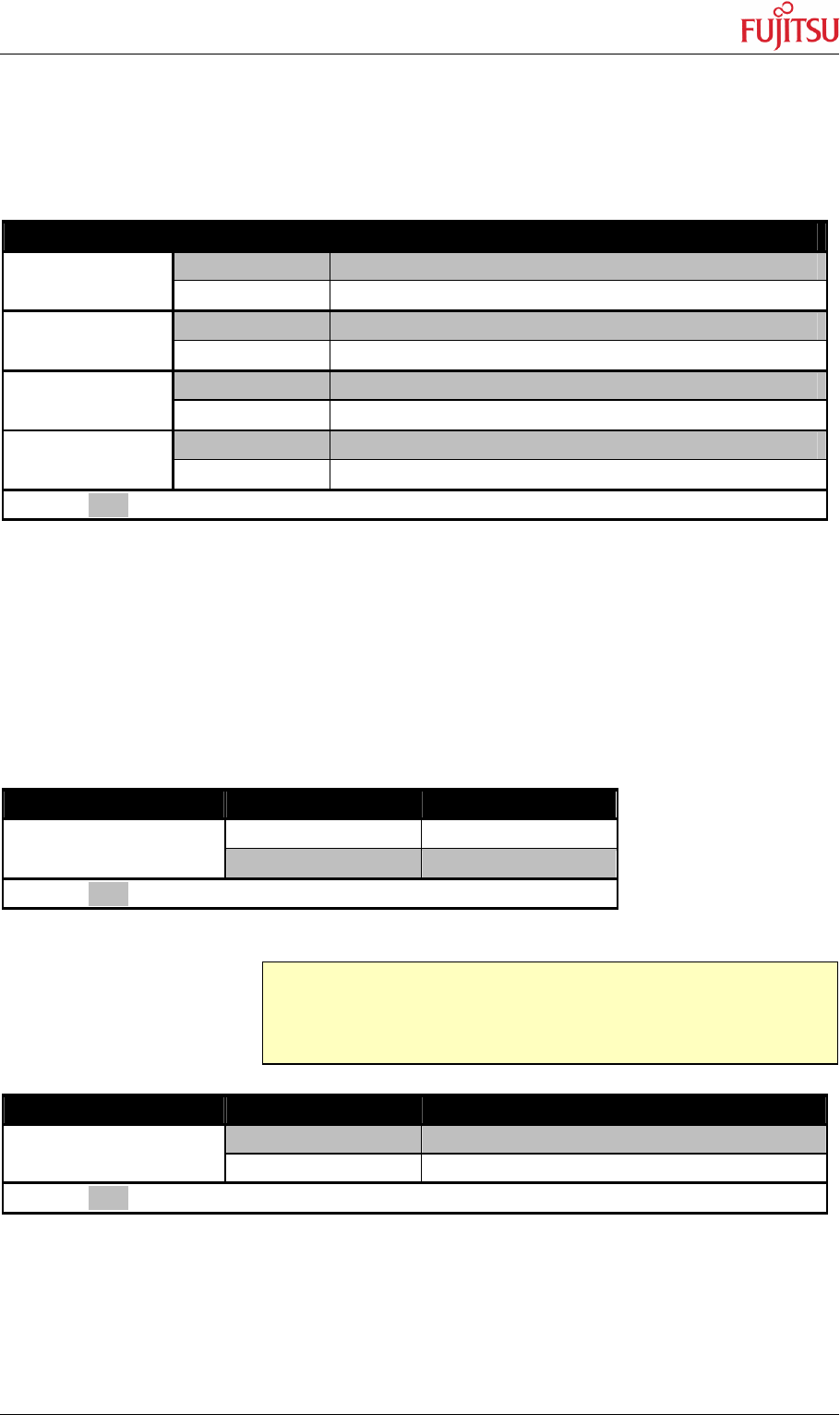
JP92 – JP95 Connects the user push buttons (SW2 – SW5) to the microcontroller
Jumper Setting Description
ON (closed) Button INT0 is connected to the microcontroller
JP92 (SW2)
OFF (open) No connection to the microcontroller
ON (closed) Button INT1 is connected to the microcontroller
JP93 (SW3)
OFF (open) No connection to the microcontroller
ON (closed) Button INT2 is connected to the microcontroller
JP94 (SW4)
OFF (open) No connection to the microcontroller
ON (closed) Button ICU0/TIN0 is connected to the microcontroller
JP95 (SW5)
OFF (open) No connection to the microcontroller
Default: grey
Table 3-19: User Push Buttons
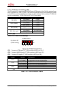
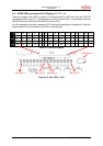
3.10 User DIP Switch 8 Bit (S4)
There is an 8 bit user-DIP-switch on-board, which can be connected to one MCU port (P26),
Connecting High- or Low level to the pins. S3, also an 8 bit DIP-switch, dis-/connect the
eight channels of S4 to the MCU pins. In case of other usage of these pins, open S3 switch
accordingly.
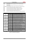
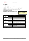
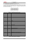
DIP switch Setting Logical value
ON (closed) 0 (low)
S4/1 - 8
OFF (open) 1 (high)
Default: grey
Table 3-20: S4 Values
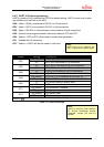
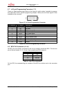
DIP switch Setting Description
ON (closed) S4/1-8 connected to MCU port P26_0-7
S3/1 - 8
OFF (open) No connection to the microcontroller
Default: grey
Table 3-21: S3 Settings
Note:
DIP-switch S3 is used to connect DIP-switch S4 to the MCU port
pins at port P26.